12.5 LEVER OF HANDLEBAR AND SEAT
12.5.1 SELF-LOCKING NUT
9
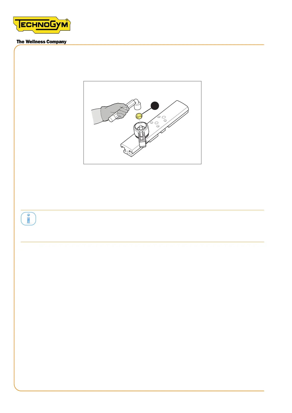
Figure 257
Every time you loosen / remove the self-locking nut (9) from the machine: it’s requested to replace
the self-locking nut with the new one. The self-locking nut must be tightened with a torque wrench
set to 3.9 Nm .
Please note that every time you replace the guides, after inserting the new guides it’s requested to
followtheproceduredescribedat§”6.1.7 REPLACING THE GUIDES”. The procedure to tighten
the self-locking nut changes.
New Group Cycle (D92):
Technical Service Guide - Rev. 5.1
Document uncontrolled when printed
Page 210