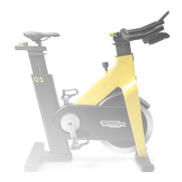
6.4 GUIDELINE ABOUT THE REPLACING OF THE
FLYWHEEL ALUMINIUM DISC AND BRAKE
CALLIPER
The ywheel aluminium disc and the brake calliper are two critical components of the Connect
version equipment. These components must be replaced only when strictly necessary.
Replacing the aluminium disc could cause a 2% decrease in the accuracy of the Wa values.
After these components are replaced, if the customer discovers a dierence between the Wa val-
ues on the display and what is actually perceived while pedalling, contact HQ After Sales Depart-
ment.
6.5 BRAKE CALIBRATION
Brake calibration must be performed:
• when removingacomponentthatinteractswiththebrakingsystem(e.g.calliper,ywheel,knob,
Hall sensor, etc.);
• when replacingtheWaSensorboard;
• when, turning the brake knob, the levels shown on the display do not change correctly,
• after launching the command ‘WRITE TORQUE TABLE’ or ‘PROGRAM WATT SENSOR
BOARD’, in the case of a Wa Sensor ID.
The brake calibration take place with the following phases:
1. Checking the alignment between the hole and the tooth of the knob (§ “6.5.1 CHECKING
THE ALIGNMENT BETWEEN THE HOLE AND THE TOOTH OF THE KNOB”).
2. Checking the calibration template, to evaluate if its size is still correct. (§ “6.5.2 CHECKING
THE CALIBRATION TEMPLATE”).
3. Mechanical regulation of the brake position. (§ “6.5.3 MECHANICAL REGULATION OF
THE BRAKE POSITION”).
4. Soft calibration. (§ “6.5.4 SOFT CALIBRATION OF THE BRAKE”).
New Group Cycle (D92):
Technical Service Guide - Rev. 5.1
Document uncontrolled when printed
Page 56