2.CONNECTION
11
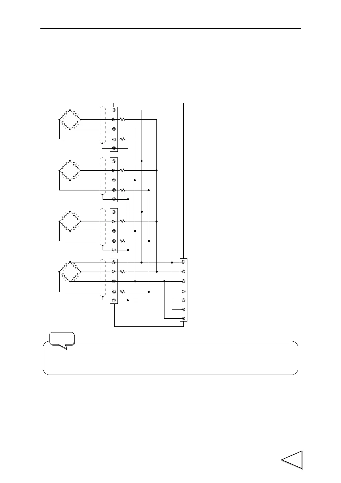
2-1-3. Connecting Load cells in Parallel
In some industrial weighing apparatus, two or more load cells may be connected in parallel to form
a hopper scale or track scale. The manner of connection is shown below.
Parallel connection can simply be made by using the optionally available B410 (summing box for
4-point multi load cell).
2-1-4. Sensor Cable
Cable colors of sensors may differ from one manufacturer to another (it may even differ from one
model to another for some products). Refer to the sensor manual (or data sheet) and check signal
names and colors in order to connect the cables correctly.
R
R
R
R
R
R
+EXC
-SIG
+SIG
-EXC
+EXC
-SIG
-EXC
+SIG
SHIELD
+S
-S
When connecting several load cells in parallel, load cell capacity should be higher than
expected load to compensate for mechanical shock or eccentric loading.
R
R
The group of “n” parallel load cells
viewed from this device side can be
regarded as a unit load cell the rated
capacity of which is multiplied by “n”
and the sensitivity of which is
unchanged. The averaging resistance (R)
should be 300 to 500Ω, equal in relative
ratio and excellent in temperature
coefficient. No averaging resistance is
needed if load cells with consideration
for parallel connection are used.
Request