2.CONNECTION
10
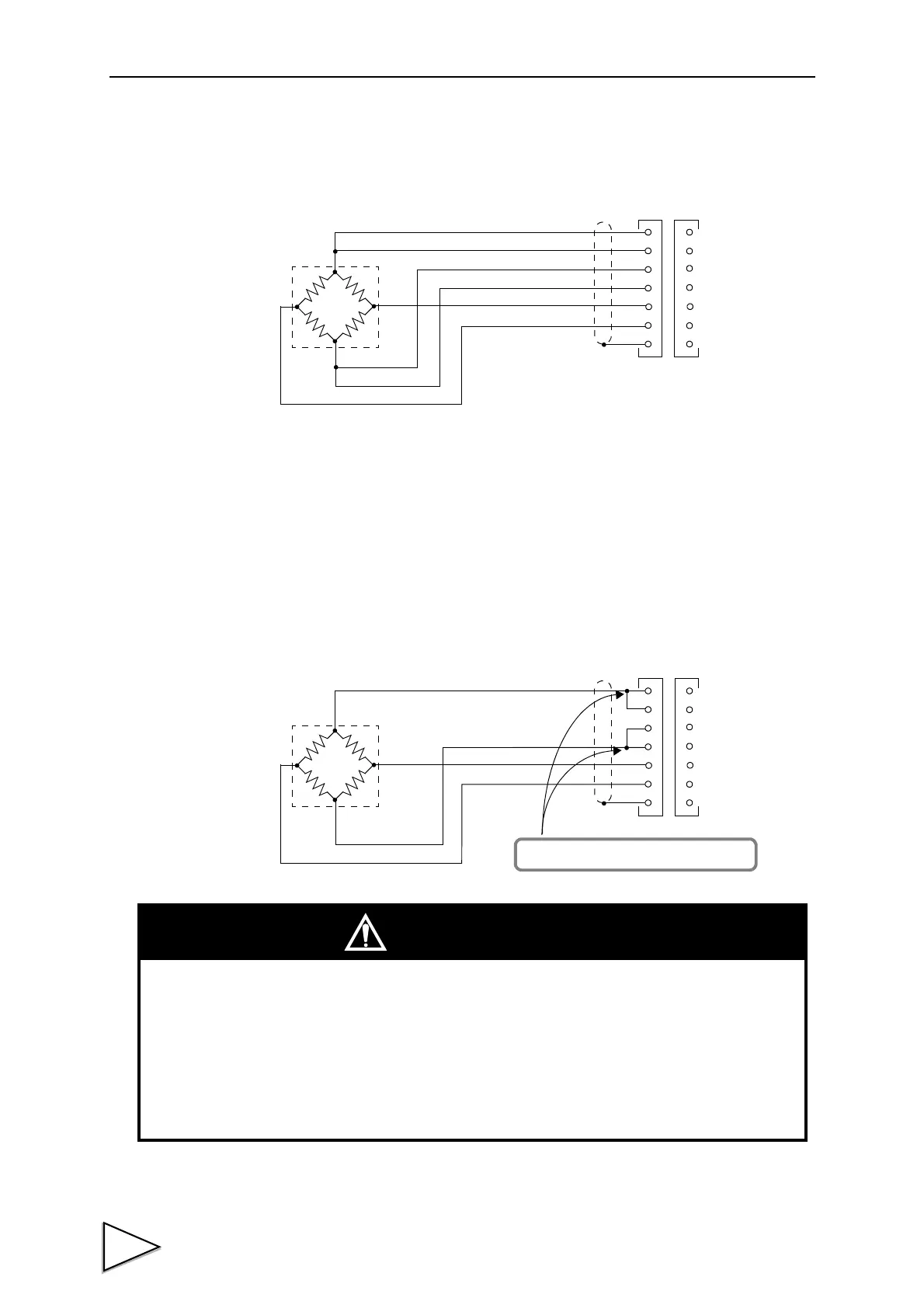
2-1-1. 6-wire Connection
The load cell input of the F701-C is a 6-wire (remote sense) connection. 6-wire shielded load cell
cable should be used and kept separate from AC or other noise generating wire.
* Remote sense lines are used to detect and correct variations in excitation voltage over long cable
runs.
2-1-2. 4-wire Connection
Connect 3 and 4, and 5 and 6 as shown below.
Even 4 and 6 on the terminal block are open, normal operation is performed apparently, but heating
or breakage may occur because excessive voltage is applied to the load cell.
For connection, use the accessory jumper lines.
+IN
-OUT
-IN
+EXC
+S
-S
-EXC
+SIG
-SIG
SHIELD
+OUT
3
4
6
5
1
2
7
Load cell
+IN
-OUT
-IN
+EXC
+S
-S
-EXC
+SIG
-SIG
SHIELD
+OUT
3
4
6
5
1
2
7
Load cell
These jumpers MUST be connected.
- The load cell excitation voltage of the F701-C is 10V. Heating or breakage may occur
unless the load cells maximum excitation voltage is 10V or more.
- When using the F701-C with the four-wire load cell connected, be sure to connect +EXC
and +S, and -EXC and -S. Even if +S and -S are not connected, normal operation is
performed apparently, but heating or breakage may occur because excessive voltage is
applied to the load cell.
CAUTION

 Loading...
