21
TECHNICAL MANUAL
12VDC
COM2
3.3V Li
BATTERY
COM1
KEYPAD
CHANNEL 3
CHANNEL 2 CHANNEL 1
SMARTWIRE
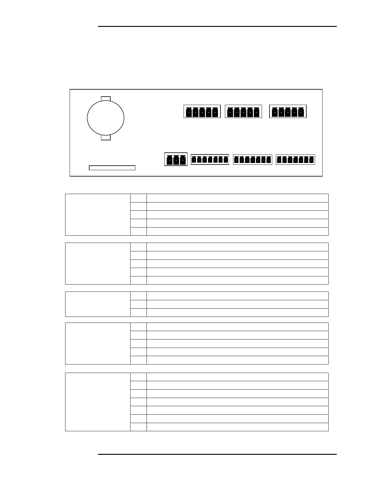
M2000A WIRING TERMINALS
All wiring to M2000 indicators terminate at the main circuit board. If
possible, all wiring to the M2000 motherboard should be done before
power is applied to the unit.
BACK OF M2000 PCB
CTS Clear To Send (Input – M2000 checks if communication is available)
RX Receive Data (Input – Data received by the M2000)
TX Transmit Data (Output – Data transmitted by the M2000)
RTS Request To Send (Output – Signals M2000 ready to receive data)
COM1
RS 232/422 PORT
COM Common (Ground)
CTS Clear To Send (Input – M2000 checks if communication is available)
RX Receive Data (Input – Data received by the M2000)
TX Transmit Data (Output – Data transmitted by the M2000)
RTS Request To Send (Output – Signals M2000 ready to receive data)
COM2
RS 232/422 PORT
COM Common (Ground)
V- (Negative)
GND (Earth ground)
MAIN POWER
CONNECTOR
12VDC
V+ (Positive power)
NC (No connection)
B (RS485 differential signal)
A (RS485 differential signal)
V+ (SMARTWIRE Power supply)
SMARTWIRE
FOR
PERIPHERAL
INTERFACE
V- (SMARTWIRE Power supply)
- EXC (Negative Excitation)
- SNS (Negative Sense)
+ SNS (Positive Sense)
+ EXC (Positive Excitation)
SHLD (Loadcell cable Shield)
- SIG (Negative Signal)
SCALE CHANNEL 1,2,3
FOR LOADCELL
CONNECTION
+ SIG (Positive Signal)