Maintenance2722−2/A1
Winterthur Gas & Diesel Ltd.
4/ 8
4. Disassemble
4.1 Injection Valve
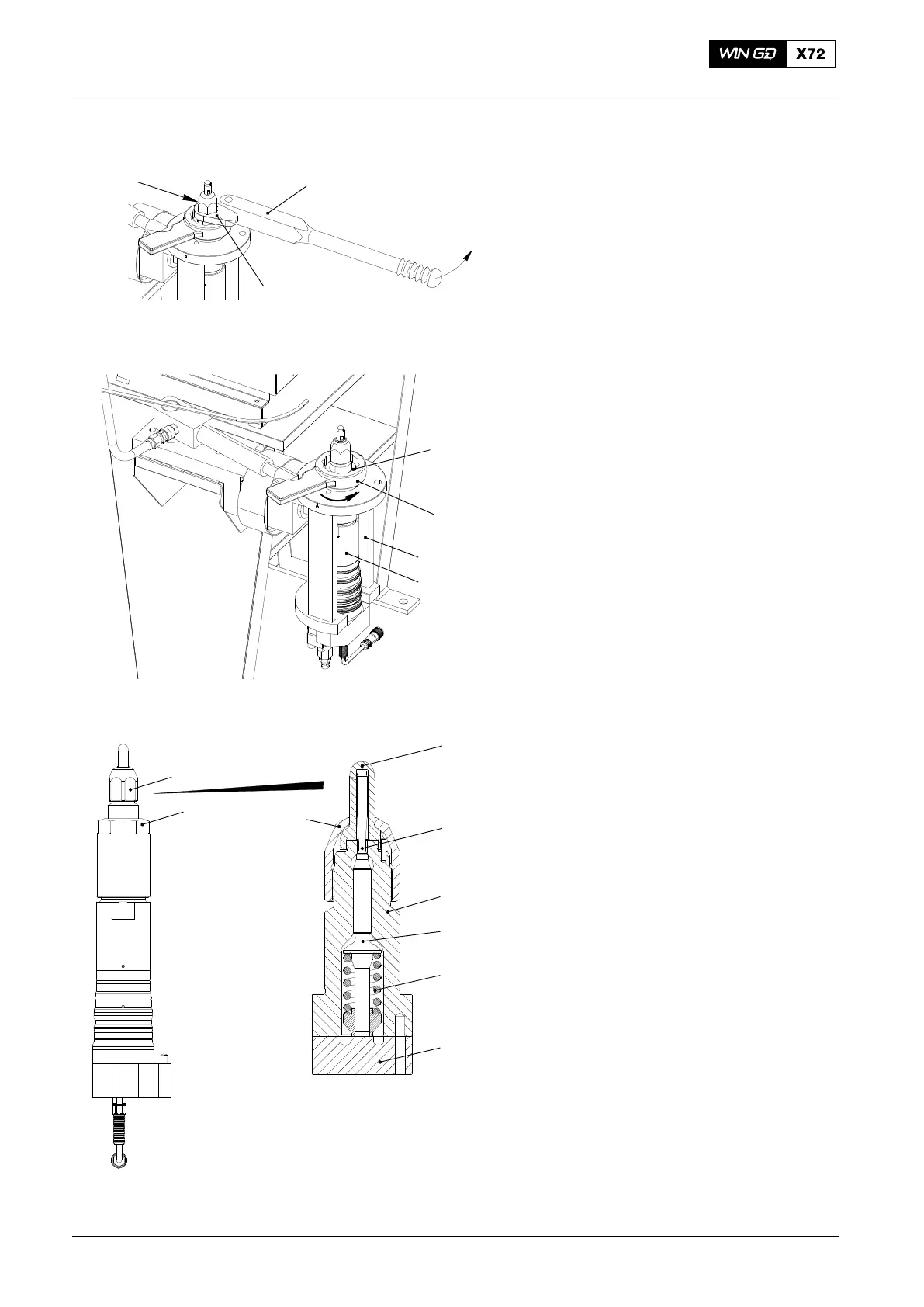
1) Make sure that the test bench has no
pressure.
2) Remove the receiver (2, Fig. 1) from
the valve holder (94273).
3) Make sure that the HP hose (94275) is
disconnected from the connecting
piece (94272B).
4) Make sure that the leakage oil hose
(94275B) is disconnected from the
injection valve.
5) Turn the valve holder through 180_ into
the vertical position (see Fig. 2).
6) Use the torque spanner (94011A) and
adapter (94269C-41) to carefully
loosen the locknut (1).
7) Remove the locknut (1).
8) Use the wrench (94269A-70) and the
hydraulic cylinder (94269B) to loosen
the coupling nut (2).
9) Remove the coupling nut (2).
10) Remove the nozzle body (8) together
with the:
D Intermediate plate (11)
D Compression spring (10).
D Tappet (9)
D Needle (7)
D Nozzle tip (6).
Note: The needle (7) and nozzle body (8)
are machined together so that their
sealing surfaces have the same
contours. You must keep these
items together. If it is necessary to
replace the needle or the nozzle
body, you must replace the two
items. Do not replace only one
item.
11) If it is necessary to remove the nozzle
tip (6) from the nozzle body (8), do the
procedure in paragraph 5.
12) Remove the intermediate plate (11).
13) Remove the compression spring (10),
the tappet (9) and the needle (7).
2015
Injection Valve: Disassemble, Checks, Assemble Injection Valve with FAST
94269C−41
94011A
94269A-70
WCH02422
94273
WCH02401
Fig. 2
1
2
3
4
5
8
11
7
9
10
6
12

 Loading...


