Maintenance
3303−4/A1
Winterthur Gas & Diesel Ltd.
1/ 9
Removal and Installation
Tools:
4 Manual ratchet, 1600kg, H1, H2 94016-009 1 Chain asymmetrical 94019B
2 Chain block, 5000kg, H3,H4 94017-021 1 Bracket 94334
1 Shackle, 8500kg 94018C 1 Connecting element 94334A
1 Chain symmetrical 94019A 1 Shackle 3250 kg 94018A
1. Preparation 1.......................................................
2. Removal 2.........................................................
3. Connecting Rod − Move 3...........................................
4. Installation 5.......................................................
5. Completion 9.......................................................
1. Preparation
1) Read the data in 0012−1 General
Guidelines for Lifting Tools.
2) Prepare the piston, refer to 3303−3,
paragraph 1, but do not turn the
crosshead to BDC.
3) Remove or lower the bottom end
bearing cover of connecting rod, see
3303−2, paragraph 2.
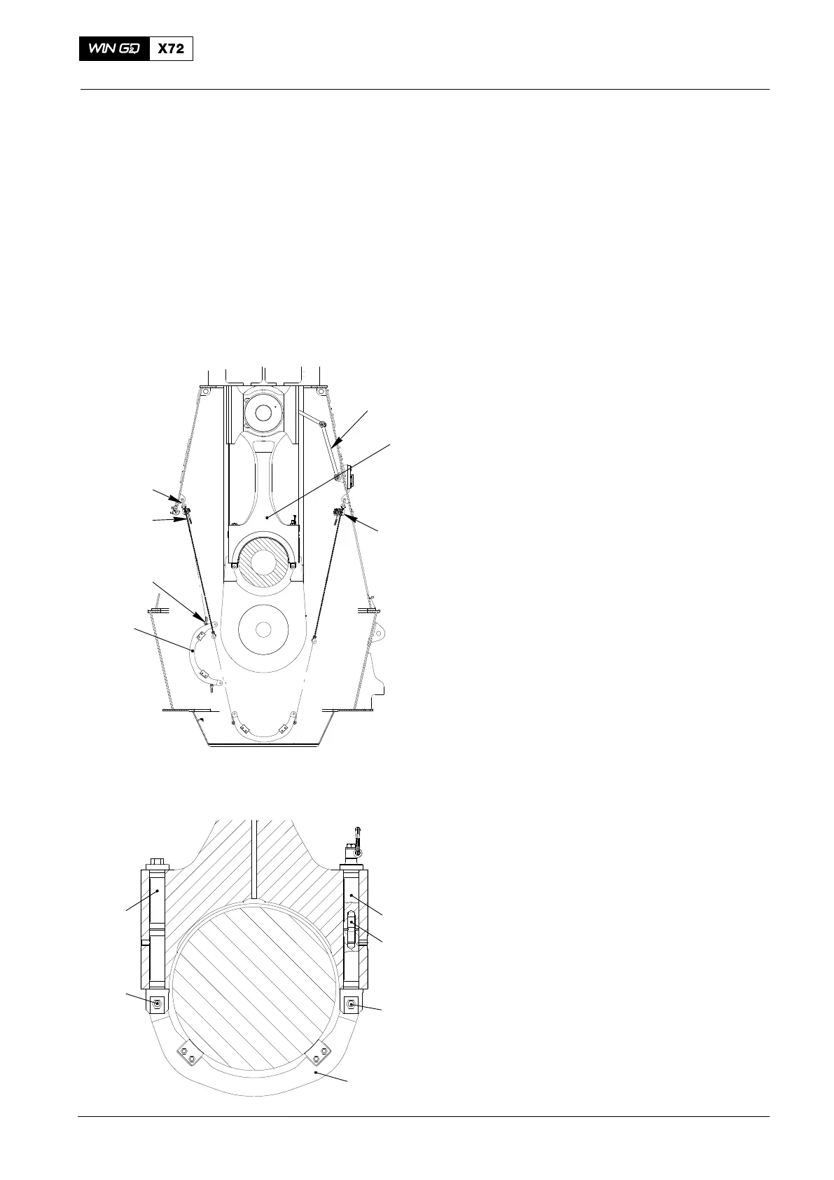
4) Attach the two shackles (94018B,
Fig. 1) and the two manual ratchets
(94016−009, H1, H2)) to the column.
5) Attach the two shackles (94018B) to
the bracket (94335).
6) Attach the manual ratchets (H1, H2) to
to the shackles on the bracket (94335).
7) Apply copper paste to the thread of pin
screw (4).
8) Put the rods (4) into the connecting rod.
9) Use the manual ratchets (H1, H2) to lift
the bracket (94335) into position on the
the rods (3).
10) Tighten the nuts and bolts (5).
11) Torque the rods (4) to 90 Nm.
12) Lift the crosshead, refer to 3303−3,
paragraph 2 and 3.
13) Remove the the manual ratchets (H1,
H2) from the plate (94335).
14) Disconnect the toggle lever (1) from the
connecting rod (2).
2015
Connecting Rod
94018A
94018A
94016-009
(H1)
94016-009
(H2)
94335
Note: Some parts can look
different. Data from W-X82
017.679/08
Fig. 1
94335
3
3
5
5
4
2
1