Maintenance
3425−1/A1
Winterthur Gas & Diesel Ltd.
5/ 9
3. Piston Ring Grooves
Do a check of all dimensions and record them (see 0330−1 Pistons and Piston
Rings). These records are important for an analysis of the running gear and must
include the data that follow:
D All dimensions
D The date of the overhaul
D The operation hours of the different components
D The operation hours of the engine.
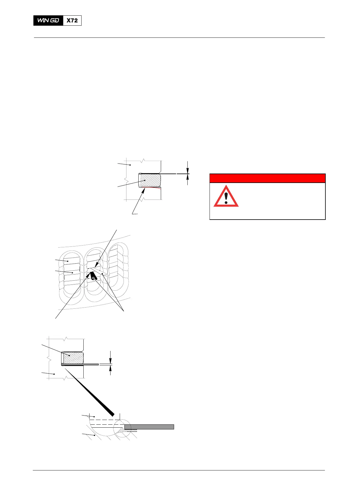
3.1 Piston Ring Clearance
(Piston Installed)
WARNING
Injury Hazard: Before you
operate the turning gear,
make sure that no
personnel are near the
flywheel, or in the engine.
1) Use the turning gear to move the piston
(2, Fig. 3) down until you can see the
piston rings.
Note: Push the feeler gage fully into the
piston ring groove. This will make
sure that the feeler gage will touch
the inner diameter of the groove.
2) Measure the clearance X1 at Point A. If
there is a wear step on the
chrome-ceramic layer, you can push
the feeler gage only to that point.
3) Measure the clearance at X2.
4) Do step 2) and step 3) at between two
and four different locations around the
piston (2).
The sum of each value from X1and X2 will
give the total piston ring clearance.
The maximum clearance is at point A. For
the maximum wear data, refer to 0330−1
Pistons and Piston Rings.
5) If the clearance at point A is more than
the permitted value, do step a) and
step b).
a) Replace the piston rings.
b) Repair the piston head.
Note: For the repair of piston heads,
speak to the nearest WinGD
Service Center.
Piston Rings: Wear of Piston Rings and Ring Grooves
2015
2
94122
1
WCH02244
Fig. 3
1
2
Wear Step On
Chrome-ceramic Layer
2
1
X2
2
1
Possible Wear
Shape On Piston
Groove
X2
X1
A
X1

 Loading...


