Maintenance
3326−1/A1
Winterthur Gas & Diesel Ltd.
1/ 1
Clearance Checks
Tools:
1 Feeler gauge 94238
1. General
During an overhaul or after the installation of
the crosshead, you must do as follows:
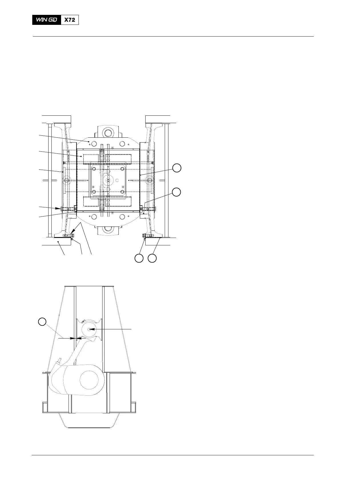
D Measure and record the clearances
shown in Fig. 1 and Fig. 2.
D Compare the clearances with those
given in 0330−1 Clearance Table.
2. Clearance Checks
2.1 Guide Shoe and Guide Way
1) Make sure that the related crank pin is
in a position so that the guide shoes(6)
touch the guide ways (3) on the fuel
side (or exhaust side).
2) Measure the clearance
j between the
guide shoe (6) and the guide way (3).
Note: The clearance
j is applicable for
the full length of the guide way (3)
and measured at the position
shown in Fig. 2.
2.2 Crosshead
1) Measure the lateral clearance k at
each position of the crosshead as
follows:
a) Use an applicable hardwood
wedge (or an item that is almost
the same) to push the crosshead
axially to one side. Make sure that
you apply the pressure only to the
guide shoe.
2.3 Guide Shoe and Top End
Bearing
1) Measure the full lateral clearance l
between the top end bearing (8) and
the the guide shoes (6).
2.4 Radial Clearance
1) Measure the radial clearance m
between the guide shoe (6) and
crosshead pin at all positions of the
crosshead.
2015
Crosshead
1
90° BEFORE OR
AFTER TDC
4
5
6
8
7
123
3
4
2 1
013.784/06
WCH02430
Fig. 1
Fig. 2
 Loading...


