Maintenance
6545−1/A1
Winterthur Gas & Diesel Ltd.
1/ 7
Maintenance
Tools:
2 Lever chain hoist 94016-009 1 Chain (asymmetric) 94019A
2 Spur gear chain block 94017-006 1 Trolley 94021
4 Shackle 94018C 2 Sling 94650
1. General 1..........................................................
2. Procedure One 2...................................................
2.1 Preparation 2.................................................
2.2 Removal 2....................................................
2.3 Installation 4.................................................
3. Procedure Two 5...................................................
3.1 Preparation 5.................................................
3.2 Removal 5....................................................
3.3 Installation 6.................................................
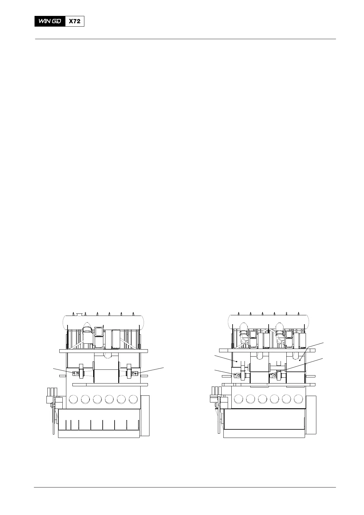
1. General
Two auxiliary blowers (2, Fig. 1) are attached to the scavenge air receiver (1). For
more data about the auxiliary blower, see the Operation Manual 6545-1 Auxiliary
Blower and Switch Box.
There are two procedures to remove and install an electric motor:
D Procedure One: For engines with one turbocharger, see the procedure given in
paragraph 2.
D Procedure Two: One of the electric motors (4) is installed between the two
scavenge air receivers (3, 6). The procedure to remove and install this electric
motor is given in paragraph 3).
Note: Also use Procedure One to remove and install the outer electric motor (5)
on an engine with two turbochargers.
For data about the procedure to clean the impeller and to replace the ball bearing,
see the documentation of the auxiliary blower manufacturer.
Fig. 1
5
4
3
2
1
WCH02413 WCH02413
6
Engine with One Turbocharger Engine with Two Turbochargers
2015
Auxiliary Blower

 Loading...


