Maintenance
9403−2/A1
Winterthur Gas & Diesel Ltd.
1/ 1
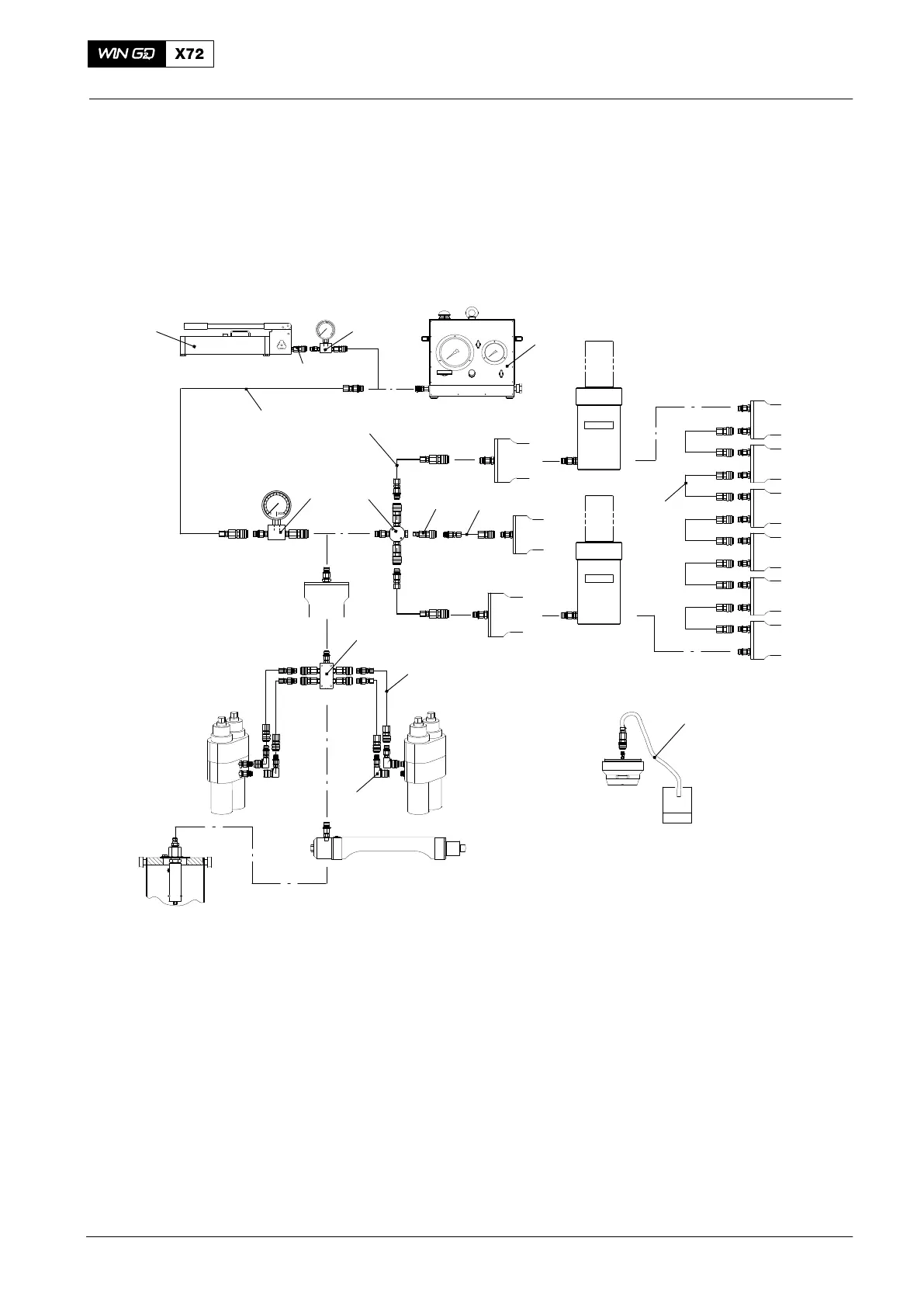
Configuration and Application
Tools:
1 HP oil Pump, 2800 bar 94931 6 Adapter piece 94934F
1a Adapter piece 94934F 7 Distributing piece 94934C
2 Hydraulic unit, 2000 bar 94942 8 Coupling element 94934G
3 HP hose 94935 9 Flexible hose 94935A
4 Pressure gauge 94934A 10 Oil pipe drain 94935C
5 Connection block 94934
1
1a
2
3
4 5
3
3
7
3
8
4
9
10
A/G
B
C
D
E
F
G
H
I
6
A For tie rods (jack: 94180), elastic studs to
exhaust valve cages and bottom connection rod
bolts (94252), top connection rod bolts (94315)
and elastic studs on supply unit (94557)
F For elastic studs to main bearing (94114)
B For elastic studs to cylinder cover (94215A) G For elastic studs to piston, piston rod and
crosshead (94340)
C Lifting the crankshaft for removal and installation
of main bearing shells (94936)
H Thrust device for main bearing cover (94110)
D Oil drain after use of pre-tensioning jacks I For checks and setting of fuel overpressure
safety valve
E For foundation bolts (94145), turning gear
(94320) and for supply unit lifting tool (94430A)
Hydraulic Jacks and Pumps
2015

 Loading...


