Maintenance
2708−1/A1
Winterthur Gas & Diesel Ltd.
1/ 5
Removal and Installation of Cylinder Cover and Water
Guide Jacket
Tools:
1 Lifting tool 94215 1 Connection block 94934
6 Pre-tensioning jacks 94215A 1 Pressure gauge 94934A
1 Suspension device 94265 3 HP hose 94935
1 Hydraulic unit 94942 5 Flexible hose 94935A
1. Preparation
1) Stop the engine, refer to the procedure
given in the Operation Manual 4002−2.
2) Let the engine temperature decrease
before you start the removal procedure.
3) Make sure that all tools and equipment
are clean.
4) Close manually the starting air supply
valves and the control air valves
(930−V03, 930−V04), refer to the
Operation Manual 4003−2 Control
Diagram.
WARNING
Injury Hazard: You must
put on safety goggles and
gloves when you do work
on hot components. Oil
can come out as a spray
and cause injury.
5) Drain the cylinder cooling water (refer
to the Operation Manual 8017−1).
6) Close the valves from the fuel supply
and make sure that there is no
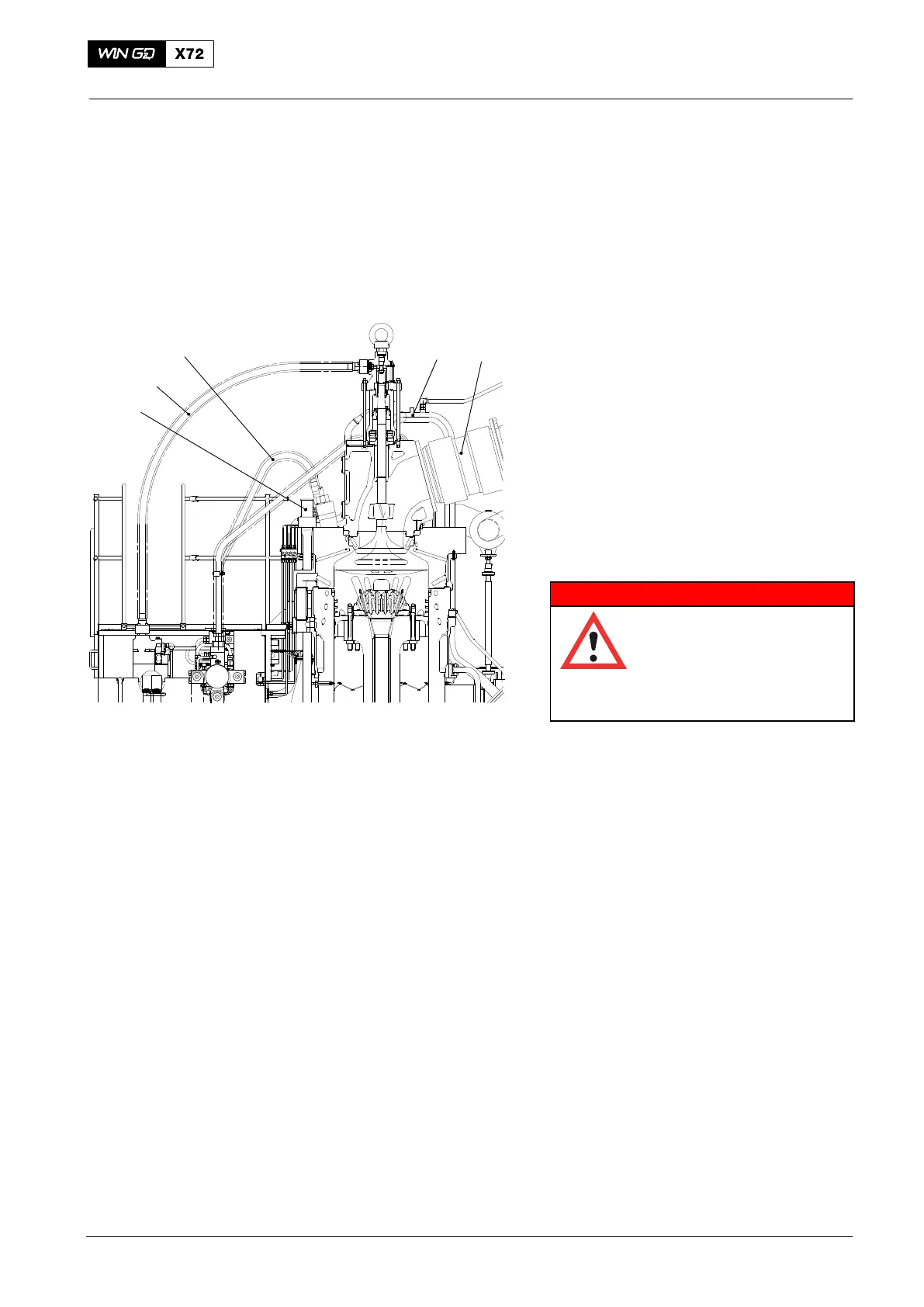
pressure in the HP fuel pipe (5, Fig. 1).
7) Remove the hydraulic pipe (4), refer to
8460−1.
8) Remove the three HP fuel pipes (5),
refer to 8733−1.
9) Disconnect the cooling pipe (1).
10) Remove the expansion piece (2), refer to 2751−1, paragraph 2, step 3) to
step 10).
11) Make sure that there is no pressure in the cooling water pipe.
12) Remove the cooling water pipe.
13) Close the starting air valve and disconnect the air pipe from the cylinder cover.
14) Disconnect all other connections from the cylinder cover and the exhaust valve.
2015
Cylinder Cover
WCH02371
Fig.1
12
3
4
5

 Loading...


