Maintenance2708−1/A1
Winterthur Gas & Diesel Ltd.
2/ 5
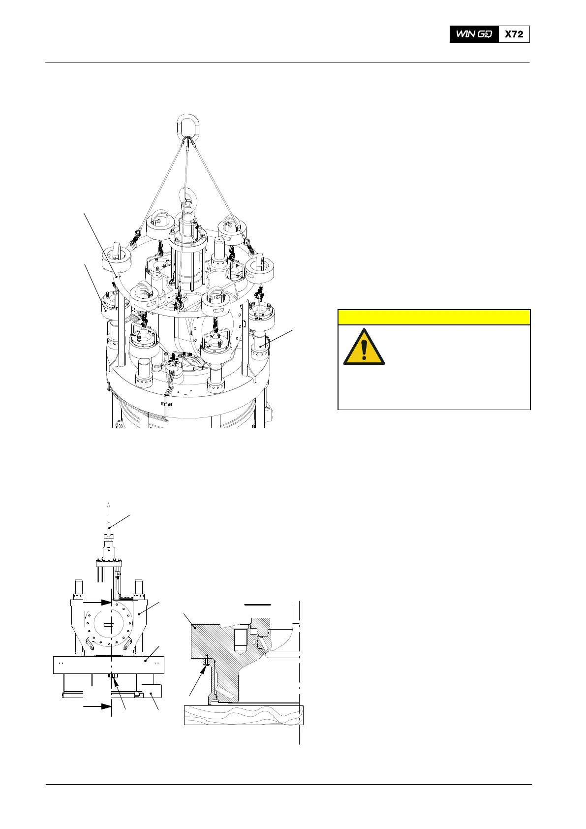
2. Removal
1) Use the engine room crane to put the
tool (94215, Fig. 2) in position above
the cylinder cover.
2) Lower the lifting tool (94215) to get the
six pre-tensioning jacks (94215A) on to
the elastic bolts.
3) Connect the jacks to the hydraulic
pump, refer to 9403−2.
4) Apply tension to the elastic bolts, refer
to 9403−4.
5) Remove the six round nuts from elastic
studs (1).
6) Remove the tool (94215).
CAUTION
Injury Hazard: The weight
of the cylinder cover with
the top water guide jacket
and the exhaust valve is
approximately 3700 kg.
Use the correct equipment
for removal.
7) Attach the engine room crane to the
eye bolt (2, Fig. 3) on the exhaust
valve (3).
8) Carefully lift the cylinder cover (4)
together with the exhaust valve (3) and
the top water guide jacket (5).
9) Lower the cylinder cover on to wooden
supports.
10) Remove the three screws (6) from the
cylinder cover (4).
Note: During step 11) make sure that the
top water guide jacket stays on the
wooden supports. If this does not
occur, use a mallet to move the top
water guide jacket.
11) Use the engine room crane to lift the
exhaust valve assembly approximately
10 mm. Make sure that the top water
guide jacket stays on the wooden
supports.
2015−06
Removal and Installation of Cylinder Cover, Water Guide Jacket, Exhaust Valve
Fig.2
3
2
6
4
5
Fig. 3
6
I
I
I - I
4
4
94215
94215A
1
WCH03225

 Loading...


