Maintenance
2708−1/A1
Winterthur Gas & Diesel Ltd.
3/ 5
)
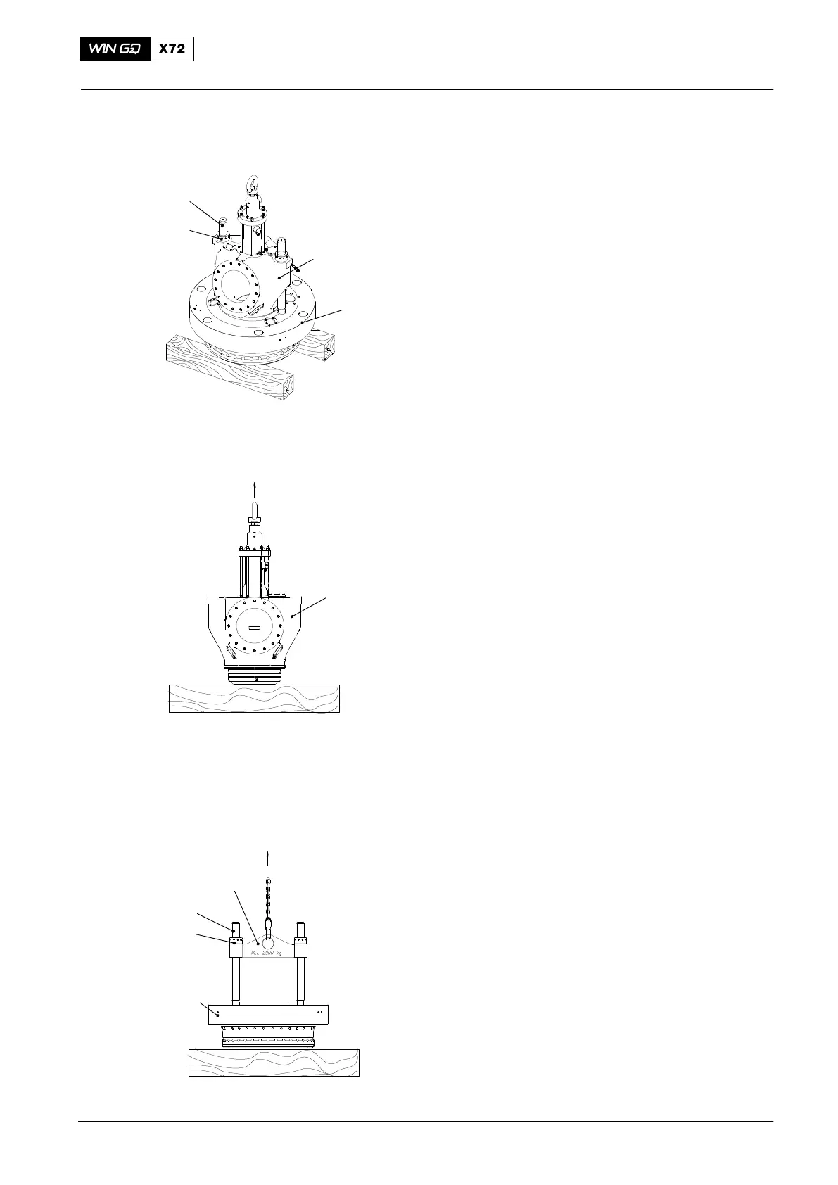
12) Lift, then lower the cylinder cover and
exhaust valve assembly (4) on to
wooden supports (Fig. 4).
13) Apply tension to the elastic studs (3) of
the exhaust valve assembly, refer to
9403−4.
14) Remove the round nuts (2).
Note: During step 16), make sure that the
cylinder cover (1) stays on the
wooden supports. If this does not
occur, use a mallet to remove the
cylinder cover.
15) Lift the exhaust valve assembly (4)
approximately 10 mm. Make sure that
the cylinder cover stays on the wooden
supports.
16) Fully lift the exhaust valve
assembly (4).
17) Carefully lower the exhaust valve
assembly (4) on to a wooden support
(Fig. 5).
18) Attach the tool (94265, Fig. 6) to the
cylinder cover as shown.
19) Attach the round nuts (2) to the elastic
studs (3).
20) Attach the engine room crane to the
tool (94265).
21) Operate the engine room crane to lift
and move the the cylinder cover (1) to
an applicable area.
22) Lower the cylinder cover on to the
wooden supports.
23) Remove the round nuts (2).
24) Remove the tool (94265).
25) Remove and discard all O-rings
26) Remove and discard the soft iron joint
ring.
2015
Removal and Installation of Cylinder Cover, Water Guide Jacket, Exhaust Valve
2
1
Fig. 5
4
Fig. 6
94265
3
1
WCH02372
3
2
4
Fig. 4

 Loading...


