Maintenance
7758−1/A1
Winterthur Gas & Diesel Ltd.
13/ 13
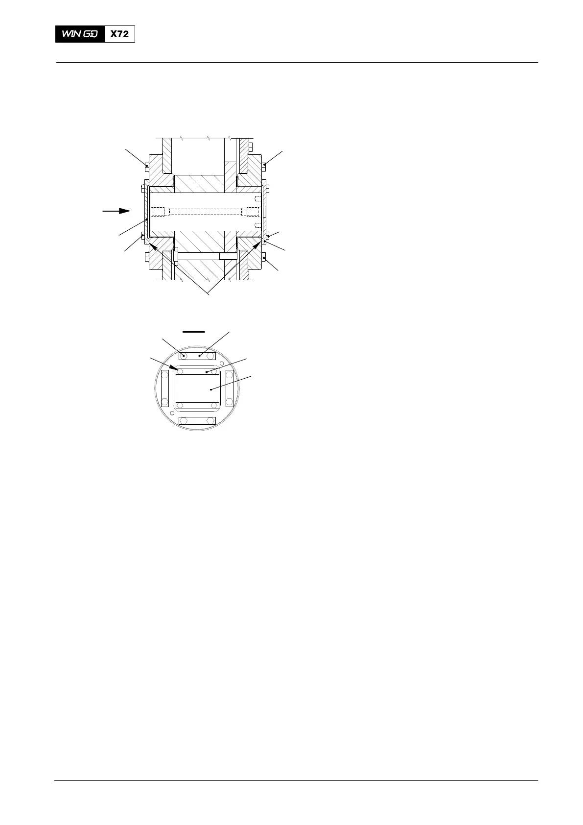
6. Final steps:
1) Install eight bolts M20x70 (6, Fig. 17)
on each bearing at outer side and
tighten them with standard torque.
2) Install eight bolts M20x70(6a) on each
bearing at engine side with locking
plates (5). Tighten bolts with standard
torque and lock them.
3) Remove alignment tools 94705.
4) Apply Loctite No. 640 to the contact
surface of bearing cover (2).
5) Install bearing cover (2) with four
screws M16x35 (1) and locking plates
(7). Tighten with standard torque and
lock the screws with locking plates.
6) Apply Loctite No. 640 to the contact
surface of bearing cover (4).
7) Install bearing cover (4) with four
screws M16x35 (3). Tighten with
standard torque.
8) Install the removed oil pipes.
9) Open the oil inlet and start the
lubricating oil supply.
2016
Integrated Electric Balancer
WCH03465
2
6
LOCTITE
Fig. 17
ENGINE SIDE
OUTER SIDE
4
3
III
5
7
6a
1
2
III
2
6a
1