Maintenance
1132−2/A1
Winterthur Gas & Diesel Ltd.
7/ 14
11) If the value of the lateral bearing clearance is more than 0.1 mm, lower the
crankshaft and do step a) to step c):
a) Install the hydraulic jacks (94936) in position where the lateral bearing
clearance is smaller.
b) Start the HP oil pump (94931).
c) Lift the crankshaft (1, Fig.15) to 0.3 mm.
4.3 Bearing Shell No.1 (narrow)
− Removal
Note: The bearing cover and the top
main bearing shell are removed.
Note: The crank is at the exhaust side at
TDC.
CAUTION
Damage Hazard: During
this procedure, use only
the applicable tools. Do
not attach external
installations. Do not use
the thrust device 94110 for
removal. Damage to
equipment can occur.
1) Make sure that the crankshaft is lifted
to 0.3 mm, refer to paragraph 4.1 and
4.2.
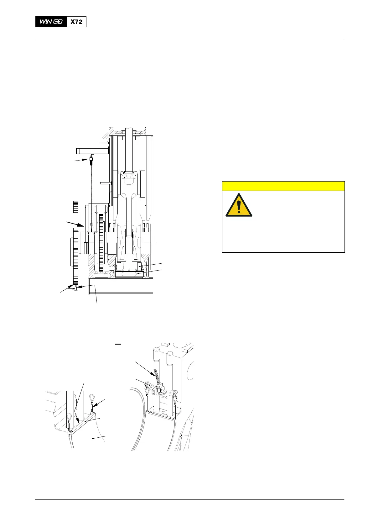
2) Attach the spur-geared chain block
(94017-005) to the eye bolt on the
platform.
3) Remove the Allen screws (1, Fig. 16)
from the bearing girder, see also Fig.
32.
4) Attach the shackle of the spur-geared
chain block (94017-005) to the lifting
plate (94119).
5) Make sure that the shackle of the
spur-geared chain block (94017-005) is
correctly attached to the middle hole of
the lifting plate (94119).
6) Attach the dismantling tool (94118A) to
the bottom main bearing shell (3).
7) Put the ropes (2) along the lateral
edges of the main bearing shell (3) to
the other side and attach them to the
lifting plate (94119) as shown.
2015
Main Bearing − Removal and Installation
94936
94141
1
Protection
I
94017−005
94118A
FUEL SIDE
1
3
EXHAUST SIDE
2
94119
94017−005
I
Fig. 16
Note: Some parts can look
different