Maintenance1132−2/A1
Winterthur Gas & Diesel Ltd.
6/ 14
4. Main Bearing Shell − Removal
4.1 Hydraulic Jacks − Installation
WARNING
Injury Hazard: Before you operate the turning gear, make sure
that no personnel are near the flywheel or in the engine.
CAUTION
Damage Hazard: Do not remove two adjacent main bearing shells
at the same time. Damage can occur to the bearing shells.
1) Operate the turning gear to turn the
crank to the exhaust side
approximately 90_ after TDC.
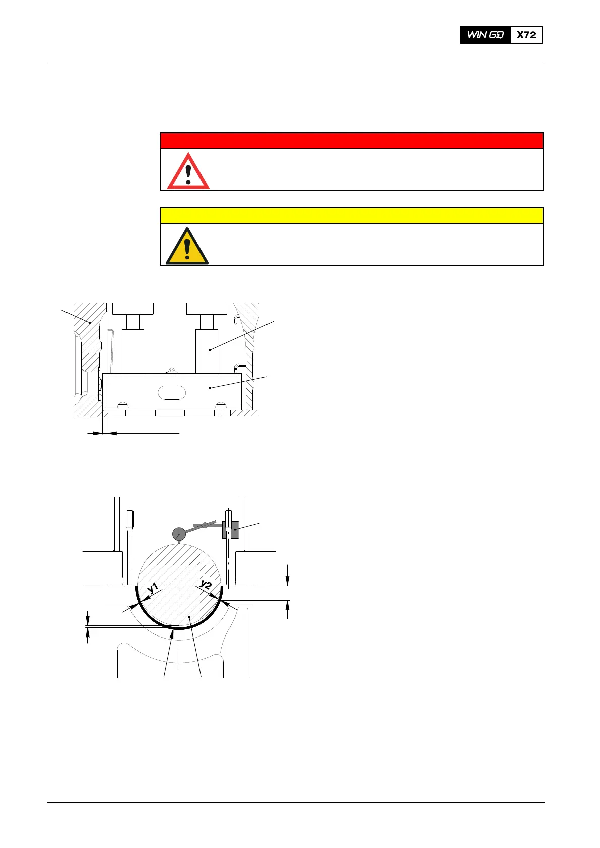
2) Put the bracket (94141A, Fig.14) on the
two main bearing girders (1) parallel to
the engine axis.
3) Make sure that the bracket is a
minimum of 43 mm from the thrust
bearing side.
4) Put the hydraulic jacks (94936) on the
bracket (94141A).
5) Connect the hydraulic jacks (94936) to
the HP oil pump (94931), refer to
9403−2.
4.2 Crankshaft − Lift
1) Record the values of the lateral
clearances (y
1
and y
2
, Fig.15) between
the crankshaft (2) and the bottom main
bearing shell (3,4) at approximately
50 mm below the bearing.
2) Install the dial gauge (1) above the
crankshaft (2) as shown
3) Set the dial gauge (1) to zero.
4) Install the jacks (94936).
5) Start the HP oil pump (94931).
6) Operate the hydraulic jacks (94936) to
lift the crankshaft (2) to 0.3 mm.
7) Make sure that the value on the dial
gauge is 0.3 mm.
8) Make sure that there is no clearance
between the adjacent bearing cover
and the crankshaft.
9) Keep the pressure constant.
10) Measure the lateral bearing clearances
y
1
and y
2.
Compare these values with
the values recorded in step 1).
2015
Main Bearing − Removal and Installation
WCH02332
94936
94141A
1
min. 43 mm
0.3mm
50 mm
009.810/02
1
23,4
Fig. 14
Fig. 15
 Loading...


