Maintenance
3403−1/A1
Winterthur Gas & Diesel Ltd.
1/ 6
Removal and Installation
Tools:
1 Lifting tool 94209 1 Piston suspension device 94341
2 Distance holders 94230 1 Insertion funnel 94342
2 Pre-tensioning jacks 94340 1 Piston support device 94350
1 Cover plate 94345D
1. Preparation 1.......................................................
2. Removal 3.........................................................
3. Installation 4.......................................................
1. Preparation
WARNING
Injury Hazard: Before you
operate the turning gear,
make sure that no
personnel are near the
flywheel, or in the engine.
1) Stop the engine, see the procedure in
Operation Manual 4002−2.
2) Let the engine temperature decrease
before you start the removal procedure.
3) Make sure that all tools and equipment
are clean.
4) Remove cylinder cover, refer to
2708−1.
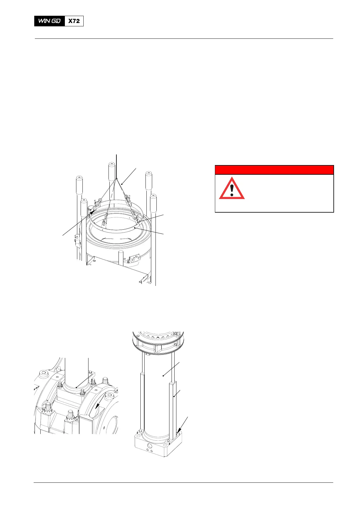
5) Attach the four plates (1, Fig. 1) of the
lifting tool (94209) to the anti-polishing
ring (2) with the four screws (3).
6) Connect the crane hook to the lifting
tool (94209).
7) Attach the lifting tool (94209) to remove
the antipolishing ring (2).
8) Remove the antipolishing ring.
9) Look at the area of the piston ring
stroke. If there is a wear ridge, refer to
the procedure in 2124−3
10) Operate the turning gear to turn the
crank to BDC.
11) Loosen the four round nuts (3, Fig. 2)
the piston rod foot, refer to the
procedure given in 9403−4 .
12) Remove the four round nuts (5).
13) Attach the two distance holders
(94230) to the piston rod foot with the
four screws (2).
2015
Piston
Fig. 1
Fig. 2
94230
WCH02460
1
3
1
2
1
2
3
94209
WCH02609

 Loading...


