Maintenance
2751−2/A1
Winterthur Gas & Diesel Ltd.
7/ 7
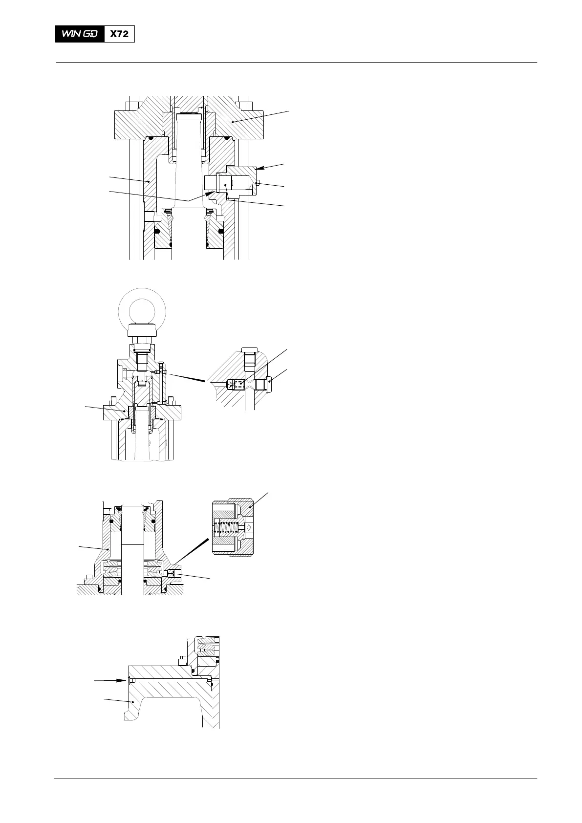
3.5 Valve Stroke Sensor −
Installation
1) Clean the parts that follow:
D The valve stroke sensor (28,
Fig. 7).
D The transmitter housing (27).
D The bore and collar in the
housing (3).
2) Put oil on the O-ring (41) and the valve
stroke sensor (28).
3) Carefully put the O-ring (41) and the
valve stroke sensor (28) into the
housing (3).
4) Attach the transmitter housing (27) to
the bottom housing (2)with the two
screws (29).
5) Connect the electrical connection to the
valve stroke sensor (28).
3.6 Throttle
1) Do a check of the throttle as follows:
a) Remove the screw plug (24,
Fig. 8).
b) Remove the throttle (23).
c) Make sure that the throttle (23) is
clear.
d) Put oil on the threads of the
throttle (23).
2) Put the throttle (23) in position.
3) Torque the throttle (23) to 4.0 Nm.
3.7 Non-return Valve
1) Do a check of the non-return valve (32,
Fig. 9) as follows:
a) Remove the non-return valve (32)
from the housing (2).
b) Make sure that the non-return
valve operates correctly.
2) Install the non-return valve (32) to the
housing (2).
3.8 Oil Supply to Valve Guide
1) Make sure that the oil bore to the valve
guide (22, Fig. 10) is clear.
2017−10
Exhaust Valve: Disassemble and Assemble
41
3
29
27
28
2
24
23
3
32
2
13
1
22
WCH02355
WCH02355
WCH02355
WCH02355
Fig. 7
Fig. 8
Fig. 9
Fig. 10