Maintenance
2751−1/A1
Winterthur Gas & Diesel Ltd.
1/ 5
Exhaust Valve − Removal and Installation
Tools:
2 Sling 94202K 1 Lifting hook 94209
1. Preparation
1) Drain the cylinder cooling water from the related cylinder (refer to the Operation
Manual 8017−1).
2) Close the air inlet to the air spring at the control air supply.
3) Remove the hydraulic pipe from the related exhaust valve, refer to 8460−1,
paragraph 1 and paragraph 2.
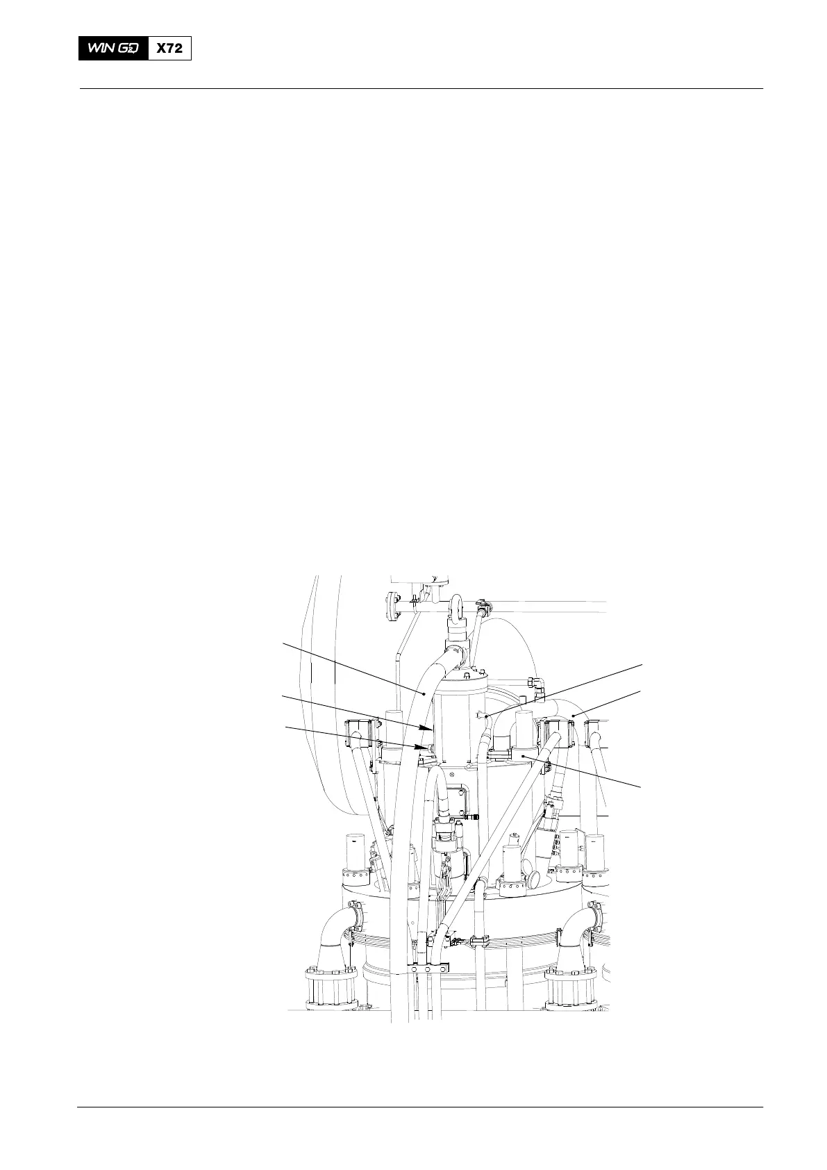
4) Disconnect the the cooling water pipe (3, Fig. 1).
5) Disconnect the the oil drain pipe (2).
6) Disconnect cable to valve stroke sensor.
7) Disconnect the air supply for the air spring (5).
2. Removal
1) Remove the round nuts, refer to the procedure given in 9403−4.
2) Disconnect the plug (2, Fig. 1) of the sensor cable from the terminal box (1).
2
Fig. 1
WCH02711
1
4
3
5
6
Exhaust Valve
2016−02

 Loading...


