Maintenance2751−2/A1
Winterthur Gas & Diesel Ltd.
4/ 7
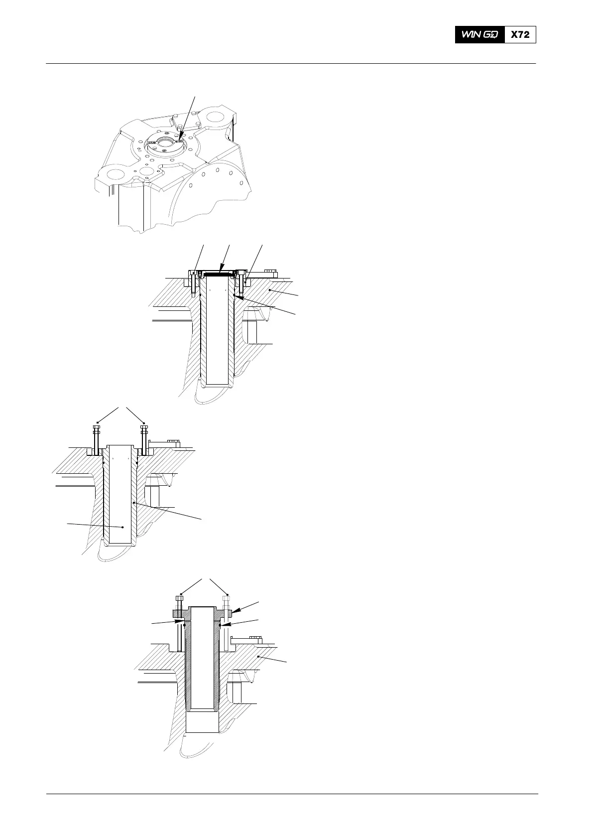
2.3 Guide Bush − Removal
1) Remove the four screws (12, Fig. 3).
2) Remove the spacer (10).
3) Remove and discard the rod seal (11).
4) Put the jack screws (94263) into the
flange of the guide bush (9).
5) Turn the jack screws (94263) to lift the
guide bush from the valve spindle (7).
6) Remove and discard the O-ring (37).
7) Measure the inner diameter of the
guide bush (9).
8) Compare the dimension with the values
given in 0330−1, Exhaust Valve.
3. Exhaust Valve −
Assemble
3.1 Guide Bush − Installation
1) Clean the bore in the valve cage (1).
2) Clean the bore in the guide bush (9).
3) Make sure that the oil bores (OB) in the
guide bush (9) are clear.
4) Install a new O-ring (37).
5) Put oil on the guide bush (9).
6) Put the guide bush (9) in position in the
valve cage (1).
7) Use the jack screws (94263) to push
the guide bush fully into the valve
cage (1).
2017−10
Exhaust Valve: Disassemble and Assemble
WCH02355
WCH02355
1
37
11
10
12
WCH02355
12
94263
9
7
9
1
OB
94263
WCH02355
37
Fig. 3

 Loading...


