Maintenance
2303−1/A1
Winterthur Gas & Diesel Ltd.
11/ 12
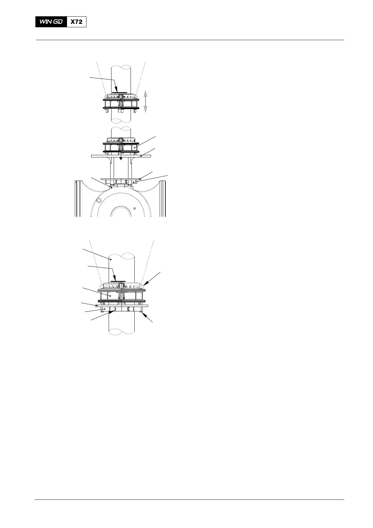
3.5 Piston rod gland −
installation
1) Lift the piston rod gland (1, Fig.16) with
two chain blocks (see chapter 3.1) to
the mark you made.
2) Remove the assembly platform 94234.
3) Lift the lifting tool 94235 together with
the support plate (5, Fig.17) up to the
piston rod gland (1).
4) Attach the lifting tool 94235 to the
piston rod gland (1) with four bolts (4).
D Make sure the dowel pin in the piston
rod gland is at the same position as the
hole in the support plate (5).
5) Tighten the four bolts (3) of the lifting
tool 94235 with 30 Nm.
6) Remove working support 94143.
7) Carefully use the turning gear to move
the piston rod gland into the cylinder
block (TDC).
8) Install working support 94143.
2016−02
Replace, Assembling, Wear Measurement
1
Fig. 16
94234
5
6
MARK
94235
Fig. 17
1
94045-M12
3
4
94235
5
7
MARK