Maintenance
5581−1/A1
Winterthur Gas & Diesel Ltd.
1/ 6
Camshaft and Bearing Shells − Removal and Installation
Tools:
2 Pre-tensioning jack 94557 1 Screwjack 94567B
2 Support 94566 1 Connection block 94934
1 or 2 Holders 94566B 1 Pressure gages 94934A
1 Holder 94566C 3 HP hoses 94935
1 Assembly template 94567 1 Hydraulic unit 94942
1 Assembly template 94567A
1. Preparation 1.......................................................
2. Bearing Shells − Removal 3.........................................
3. Camshaft − Removal 4..............................................
4. Camshaft and Bearing Shells − Installation 4.........................
5. Completion 6.......................................................
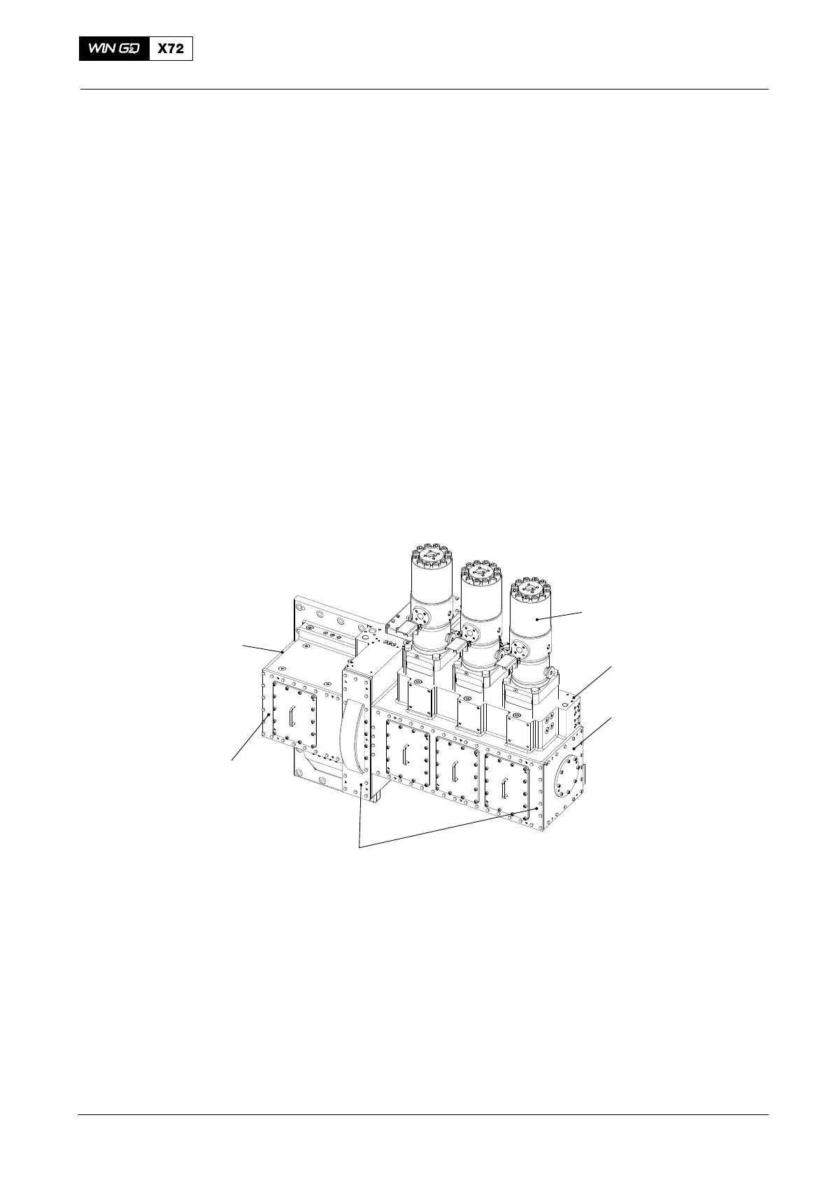
1. Preparation
1) Remove the covers (3, 4, 5, and 6, Fig. 1) from the housing (2).
2) Remove the fuel pumps (1) see 5556−1, or as an alternative lift the rollers (see
step 3) to step 4).
6
1
2
4
WCH02236
3
5
Fig. 1
2015
Supply Unit

 Loading...


