Maintenance
3303−2/A1
Winterthur Gas & Diesel Ltd.
1/ 7
Bottom End Bearing − Removal, Inspection and
Installation
Tools:
2 Manual ratchet H1/H5 1600kg 94016-009 4 Eye bolt M8 94045-M8
2 Manual ratchet H2/H3, 2500kg 94016-011 1 Deviation pipe 94117B
1 Manual ratchet H4, 6300kg 94016-017 1 Pre-tensioning jack 94252
4 Shackle, 4750 94018B 1 Chain 94327
2 Shackle, 8500 94018C 1 Console Frame 94326
1 Chain, 5300kg 94019B 1 Support 94322
1 Support (for iELBA) 94322A
1. Preparation 1.......................................................
2. Bearing Cover − Removal 1.........................................
3. Bearing Shell − Removal 2..........................................
4. Top Bearing Shell − Inspection 3.....................................
5. Top Bearing Shell − Removal 4......................................
6. Top Bearing Shell − Installation 5....................................
7. Bottom Bearing Shell − Installation 6.................................
8. Bearing Cover − Installation 6.......................................
1. Preparation
WARNING
Injury Hazard: Before you
operate the turning gear,
make sure that no
personnel are near the
flywheel, or in the engine.
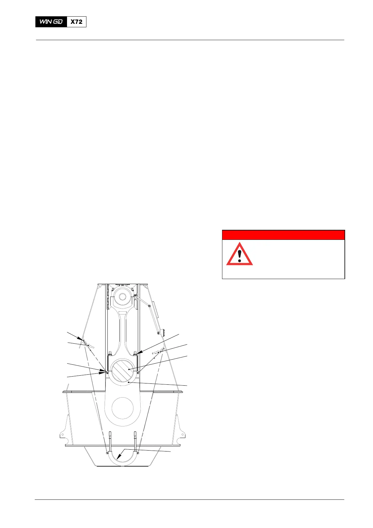
1) Use the turning gear to turn the
crankshaft until the applicable crank (2,
Fig. 1) is at TDC.
2) Lock the turning gear.
3) Attach the eye bolts (94045-M8) to the
bearing cover (3).
4) Attach the shackles (94018B) to the
column.
5) Attach the manual ratchets (H2, H3) to
the shackles (9418B) and the eye bolts
on the bearing cover (3).
6) Apply a light tension the manual
ratchets H2 and H3.
2. Bearing Cover −
Removal
1) Loosen the round nuts (1), refer to
9304−4 paragraph 2.
2) Remove the round nuts (1).
3) Carefully lower the bearing cover (3).
4) Examine the bearing shell (4).
Note: If the bearing shell is in good
condition, lower the bearing cover
on to the bottom of the crankcase.
2015
Connecting Rod
EXHAUST SIDE
H2
2
3
94045-M8
H3
94018B
94018B
1
4
WCH02423
Fig. 1