Maintenance
7758−1/A1
Winterthur Gas & Diesel Ltd.
9/ 13
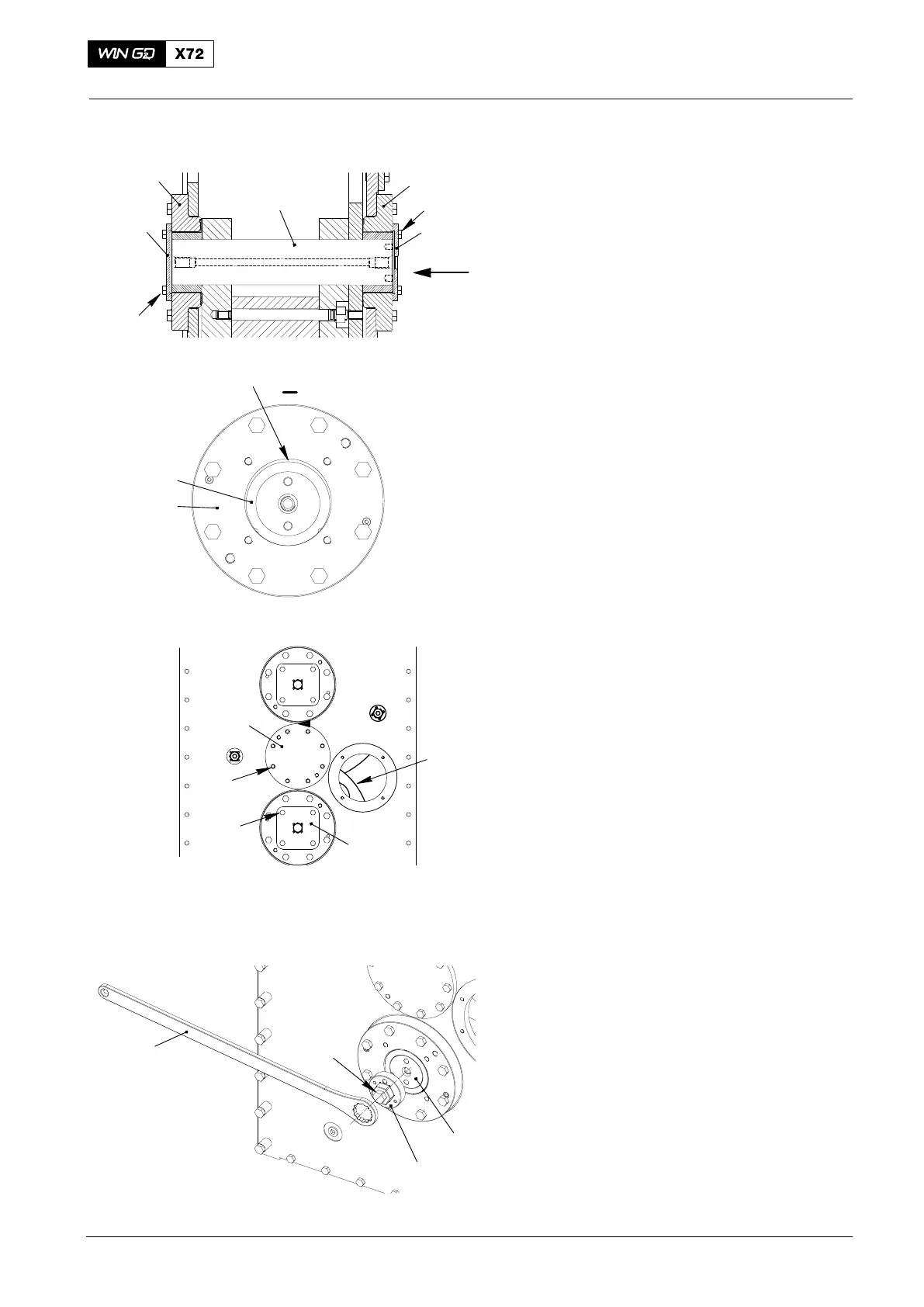
5. Check
5.1 Bearing clearance
1) Remove the four screws (5) and the
locking plates on the bearing cover (4)
at the engine side.
2) Remove the bearing cover on the
engine side.
3) Remove the four screws (7) on the
bearing cover (6) at the outer side.
4) Remove the bearing cover (6).
5) Use a feeler gauge to measure the
clearance between pin (1) and bearing
(2) and (3) at the upper position (FG).
6) Compare clearance with the data given
in 0330−1.
7) Replace bearing if clearance is more
than the allowed maximum clearance.
8) For the first time, it’s recommended to
call WinGD for expert advice.
5.2 Measure Backlash
1) Remove the eight screws (4, Fig. 11)
and the cover (5).
2) Make sure the clamping screws (4, Fig.
2) are removed.
3) The service hole (8) to measure the
backlash between motor pinion and
lower gear wheel is reachable from
inside the engine.
4) Remove the four screws (7) on the
lower bearing cover (6) at the outer
side.
5) Install turning device 94703 for turning
the gear wheels, as follows:
D Install the socket insert (5, Fig 12) with
the screw (6) on the pin (4) of the lower
bearing. Tighten the screw (6) with
100 Nm.
2016
Integrated Electric Balancer
FG
5
I
I
6
ENGINE SIDE
OUTER SIDE
4
1
3
2
7
1
2
Fig. 10
6
7
Fig. 11
WCH03465
4
5
8
94703
5
Fig. 12
6
4

 Loading...


