Maintenance7758−1/A1
Winterthur Gas & Diesel Ltd.
8/ 13
4.2.2 Installation
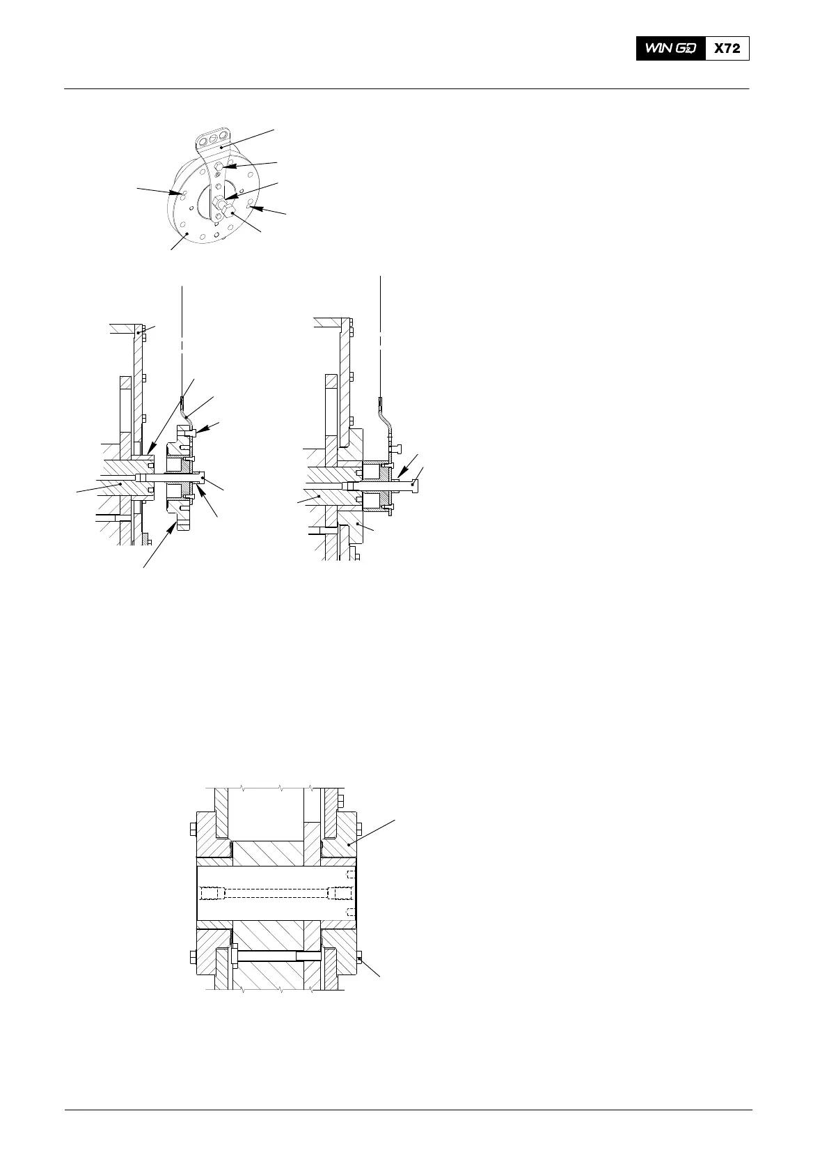
1) Make sure that the new bearing (6, Fig.
8) is clean, dry and in good condition.
Apply Molycote D to the bearing
surface.
D Do not install the two taper pins (8, Fig.
9).
2) Attach the lifting 94704 tool to the new
bearing (6, Fig. 6). Tighten screw (2).
3) Lift bearing (6) in front of the pin (3).
4) Apply Loctite No. 640 to the contact
surface of the bearing (6).
5) Apply Molycote D to the bearing
surface of pin(3).
6) Install screw (4) together with nut (5)
through the bearing (6) into the pin (3).
7) Remove screw (2).
8) Locate the taper pin bores in the cover
(1) and turn the new bearing until the
pin bores in the bearing (6) are 90° to
the ones in the cover.
9) Tighten nut (5) and guide the bearing
(6) in the correct position on the
column (1) (STEP 2).
D Use the crane if the pin (3) is too low.
10) Remove lifting tool 94704.
11) Install four (of eight) bolts M20x70 (2,
Fig. 9) without tightening.
12) Adjust the backlash and the parallelism
of the gear wheels, refer to chapter 5.2.
2016
Integrated Electric Balancer
94704
2
5
4
6
LOCTITE
MOLYCOTE D
3
4
5
2
94704
1
Fig. 8
8
8
STEP 1
ENGINE SIDE
OUTER SIDE
4
STEP 2
3
5
6
WCH03465
2
6
Fig. 9
ENGINE SIDE
OUTER SIDE


 To Next Page