Maintenance
7758−1/A1
Winterthur Gas & Diesel Ltd.
3/ 13
2. Preparation
1) Stop the engine, refer to Operation
Manual, 0310−1.
2) Make sure that the electric motor (5,
Fig. 1) has stopped.
3) Stop the lubricating oil supply and close
the oil inlet.
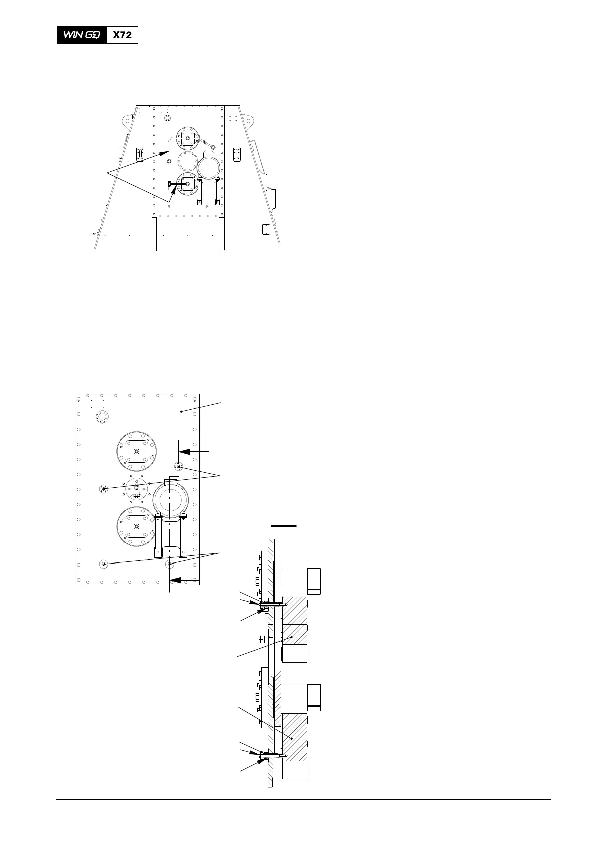
4) At driving end, put an oil tray under
applicable oil pipe (1, Fig.2).
5) Remove the applicable oil pipe (1) to
get access to the balancer shafts.
3. Counterweights − Lock
3.1 Top Counterweight
1) Apply lubricating oil to the thread and
bottom of the head of the clamping
screw (4, Fig. 3) and the nut (6).
2) Remove the two screws (2) from the
main cover (1).
3) Put the two clamping screws (4) and
the nuts (6) in position on the upper
counterweight (10).
4) Torque the clamping screws (4) to
60 Nm.
5) Torque the nut (6) to 60 Nm.
6) Put the the M12 bolt (5) in position
through the clamping screw (4).
7) Torque the M12 bolt (5) to 60 Nm.
3.2 Bottom Counterweight
1) Apply lubricating oil to the thread and
bottom of the clamping screw (7) and
the nut (9).
2) Remove the two screws (3) from the
cover (1).
3) Put the two clamping screws (7) and
the nuts (9) in position on the lower
counterweight (11).
4) Torque the clamping screws (7) to
60 Nm.
5) Torque the nut (9) to 60 Nm.
6) Put the M12 bolt (8) in position through
the clamping screw (7).
7) Torque the M12 bolt (8) to 60 Nm.
2016
Integrated Electric Balancer
WCH03566
DRIVING END
1
1
2
3
I
I
WCH03465
4
5
6
I - I
7
8
9
10
11
Fig. 2

 Loading...


