Maintenance
2303−1/A1
Winterthur Gas & Diesel Ltd.
5/ 12
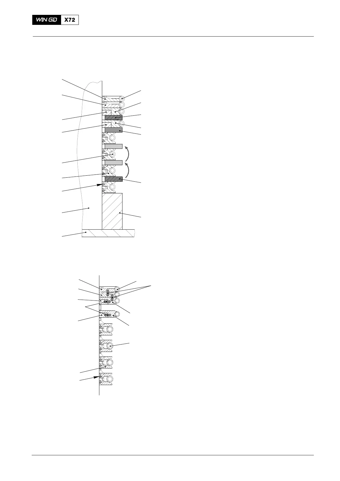
2.4 Piston rod gland − assemble
1) Attach the two parts of the clamp ring
94231A to the piston rod (see Fig. 7).
2) Put the three parts of the ring support
(15) and the scraper rings (16) on the
clamp ring 94231A.
3) Use the assembly tool 94233 to attach
the tension spring (20) to the ring
support (15).
4) Put the two parts of the distance piece
94231D (9 mm height) on the ring
support (15) (see Fig. 7).
Note: The height of the distance piece
94231C is the same as the distance
between the ring grooves in the
housing.
5) Put the next three parts of the ring
support (15) and the scraper rings (16)
on the distance piece. Make sure that
there is an equal distance between the
three parts.
6) Use the assembly tool 94233 to attach
the tension spring (20) to the ring
support (15).
7) Remove the distance piece 94231D.
8) Do the steps 4) − 7) above again until
the four ring supports (15) are attached
to the piston rod 22.
9) Put the two parts of the distance piece
94231C (11 mm height) on the top ring
support (15).
Note: One segment of the gaskets (12,
13, 14) has two holes for the
horizontal spring dowel pins (18)
(see Fig. 8). The other three
segments have only one hole. On
the top of one segment of the
gasket (13) there is one hole for a
vertical spring dowel pin (17).
10) Put the four parts of the gaskets (12,
14) on the distance piece 94231C (see
Fig. 7).
11) Make sure that all horizontal spring
dowel pins (18) are installed (see
Fig. 8).
12) Use the assembly tool 94233 to attach
the tension spring (19) to the
gaskets (12, 14).
13) Remove the distance piece 94231C.
2014
Replace, Assembling, Wear Measurement
Fig. 7
22
94345F
94231D
94231A
23
16
15
19
12
11
20
10
13
14
12
WCH02292
94231C
Fig. 8
16
15
19
12
11
10
13
14
12
20
WCH02292
18
17