Maintenance1132−2/A1
Winterthur Gas & Diesel Ltd.
8/ 14
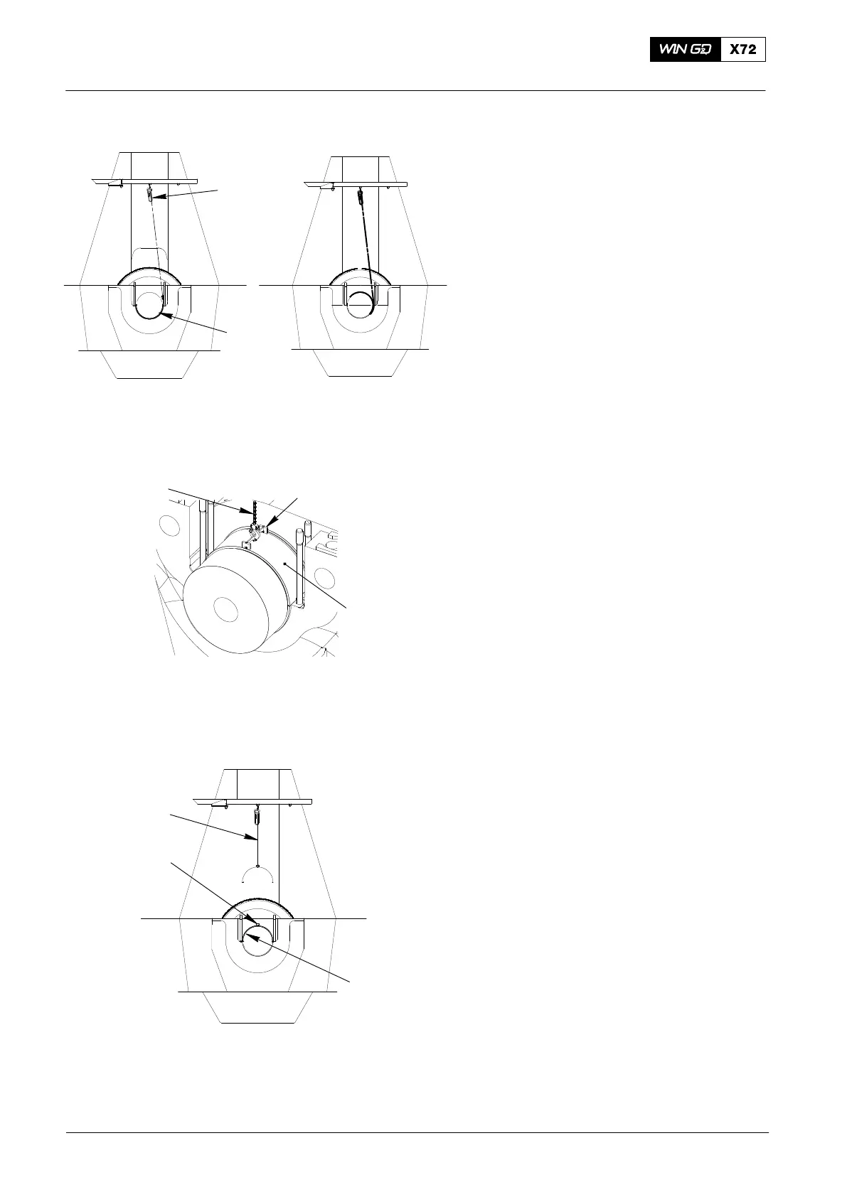
8) Operate the spur-geared chain block
(94017-006, Fig. 17) to turn the bearing
shell (1) as shown in Fig. 18 and
Fig. 19.
Note: If the bearing shell (1) does not
move, the lifting plate (94119,
Fig. 16) must be attached to the
other side of the dismantling tool
(94118A). The bearing shell must
be moved back to its initial
condition and you must do the
removal procedure done again.
9) Remove the bearing shell (1, Fig. 19)
out as shown in Fig. 20.
10) Remove the dismantling device
(94118A).
11) Install the lifting tool (94116B) to the
bearing shell (1).
12) Remove the spur-geared chain block
(94017−005) from the lifting plate
(94119).
13) Attach the spur-geared chain block
(94017−005) to the lifting tool (94116B).
14) Remove the lifting plate (94119).
15) Operate the spur-geared chain block
(94017−006) to lift the bearing shell (1).
16) Move the bearing shell (1) to an area
where you can operate the engine
room crane.
17) Attach the engine room crane to the
bearing shell.
18) Remove the spur-geared chain block
(94017−006).
19) Operate the engine room crane to
move the bearing shell to a safe area.
2015
Main Bearing − Removal and Installation
1
94017−006
1
94116B
94116B
94017−006
94017−006
Fig. 17
Fig. 18
Fig. 19
Fig. 20
1