Maintenance2708−1/A1
Winterthur Gas & Diesel Ltd.
4/ 5
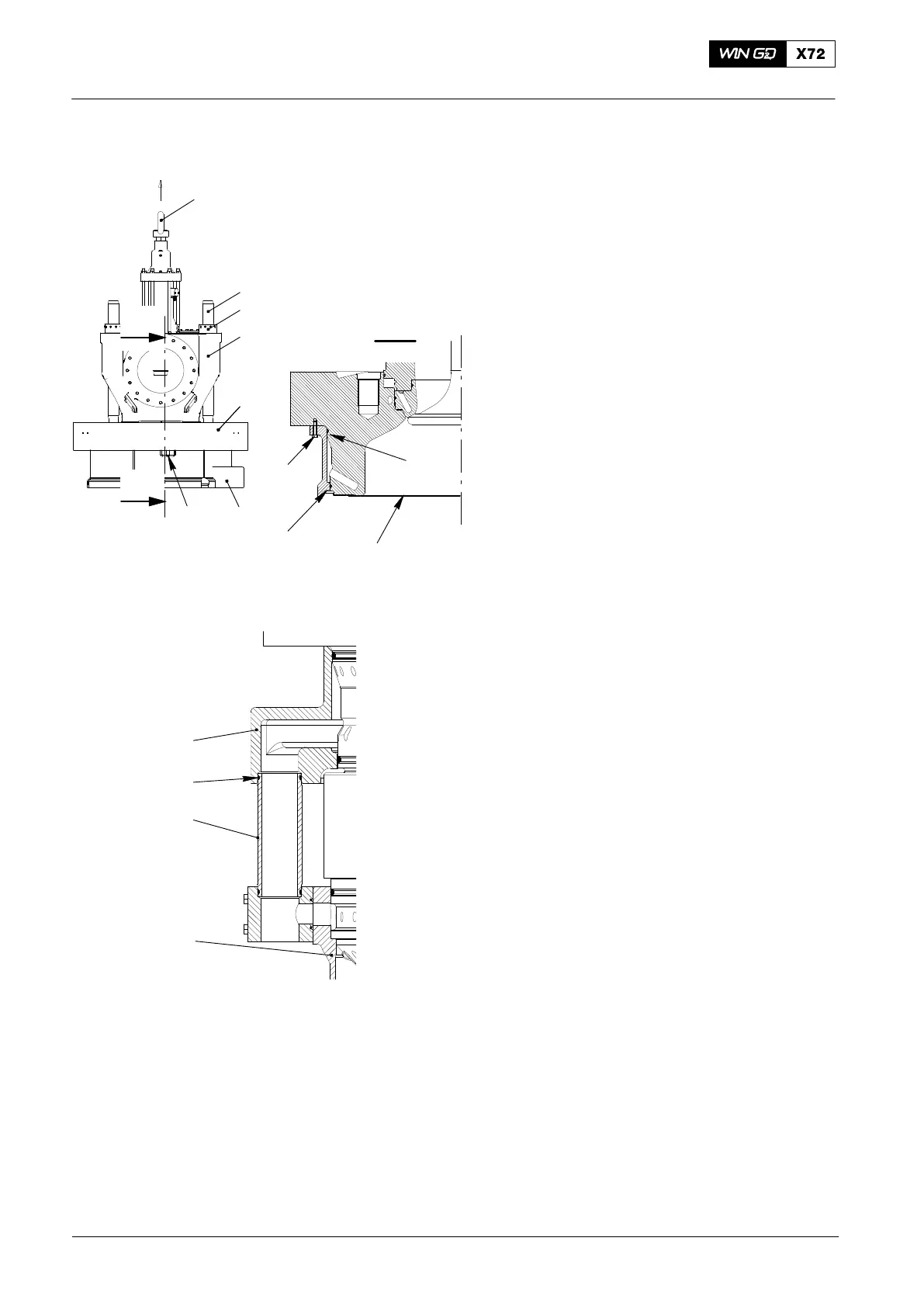
3. Installation
1) Clean the O-ring grooves.
2) Clean the sealing surfaces of the
cylinder cover.
3) Put oil on the new O-rings (8 and 10,
Fig. 7).
4) Install the new O-rings (8, 10).
5) Put a new soft iron joint ring (9) in
position in the cylinder liner.
6) Put oil on the new O-ring (12).
7) Put the O-ring (12) on the transition
tube (13).
8) Clean the threads of all the elastic
studs.
9) Put oil on the threads of all the elastic
studs.
10) Attach the engine room crane to the
eye bolt (1).
11) Lift the exhaust valve assembly (4).
12) Carefully lower the exhaust valve
assembly (5) on to the cylinder
cover (6).
13) Attach the round nuts (3) to the elastic
studs (2).
14) Apply tension to the elastic studs (2),
refer to 9403−4, then tighten the round
nuts (3).
15) Operate the engine room crane to lift
the cylinder cover (5) together with the
exhaust valve assembly (4).
16) Carefully lower the cylinder cover (4)
on to the top water guide jacket (5).
17) Attach the top water guide jacket (5) to
the cylinder cover (4) with the three
screws (6).
18) Operate the engine room crane to lift
the cylinder cover (5) together with the
exhaust valve assembly (4) and water
guide jacket (6).
Note: During step 19), make sure that the
tube (13) goes into the bore in the
top water guide jacket (6).
19) Carefully lower the cylinder cover (5)
together with the exhaust valve
assembly (4) and water guide jacket (6)
on to the cylinder liner (14).
20) Remove the engine room crane from
the eye bolt (1).
2015
Removal and Installation of Cylinder Cover, Water Guide Jacket, Exhaust Valve
12
13
6
WCH02375
14
Fig. 7
4
1
7
5
6
11
I
I
I - I
9
10
8
2
3

 Loading...


