Maintenance
3303−3/A1
Winterthur Gas & Diesel Ltd.
3/ 8
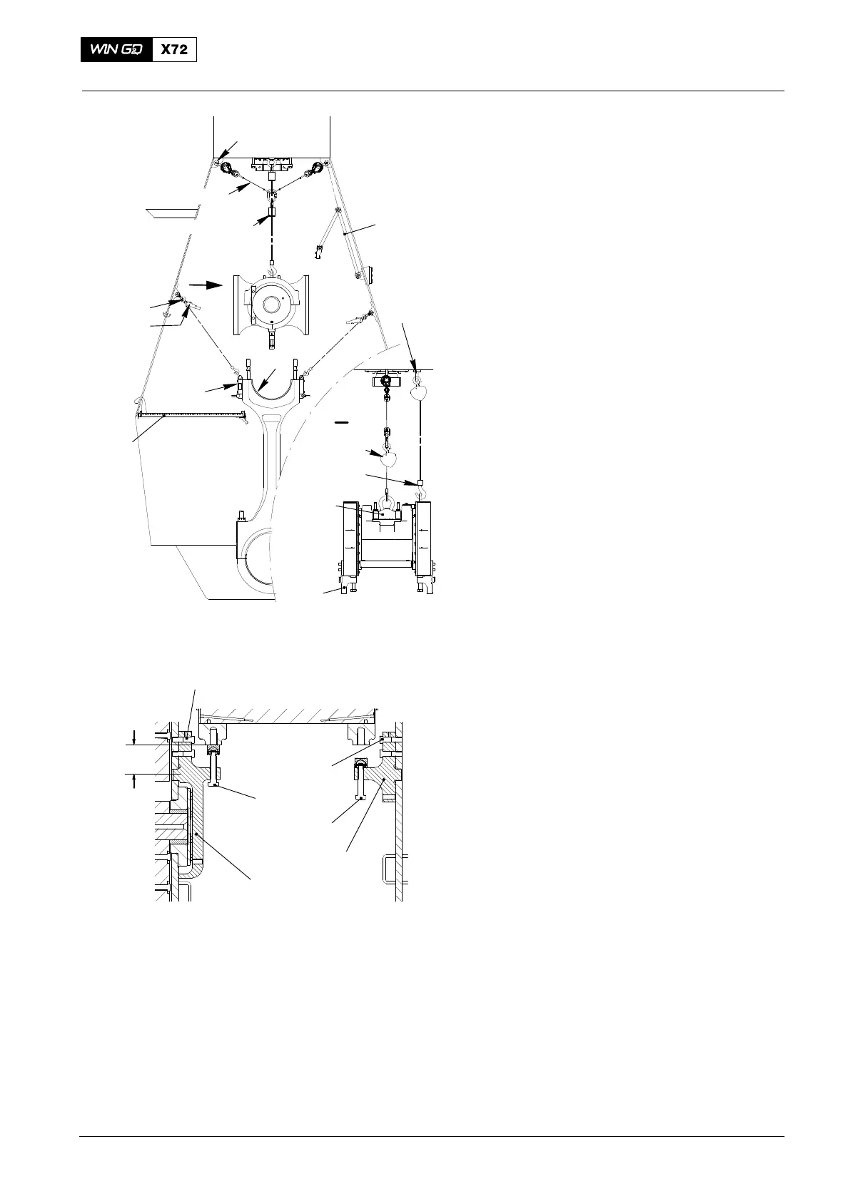
3. Crosshead − Lift
1) Attach the shackles (94018B, Fig. 4) to
each side of the column.
2) Attach a manual ratchet (H1, H2) to the
shackles (94018B) and the the two
lifting tools (94337).
3) Apply a light tension to the manual
ratchets (H1, H2).
Note: If the cylinder cover and piston are
removed you can use the engine
room crane and chain block H4 to
lift the crosshead.
4) Attach the chain (94019B) to the two
shackles (94018C).
5) Attach the manual ratchet (94016-017,
H3) to the chain (94019B).
6) Attach the manual ratchet (94017-21,
(H4) to the eye bolt (94045-M48) at the
top of the column and the eye bolt on
the bearing cover, see View I.
7) Operate the chain block (H3) to lift the
crosshead approximately 300 mm
above the plug bore center (see Fig. 5)
in the column.
8) Keep the tension on the chain block
(H4, Fig. 4).
Note: Fig. 5 shows an engine with
electric Balancer (iELBA). Use two
supports 94322 for engines
without balancer.
9) Attach the two supports (2x 94322 or
for iELBA: 1x 94322A and 1x 94322)
with the four bolts (1, 4, Fig. 5).
10) Torque the four bolts (1,4) to 300 Nm.
11) Lower the crosshead for 140 mm
(160 mm above plug bore center).
12) Tighten the special screws (2, 3).
13) Inspect the bearing shell 13.
14) If it is necessary to replace the bearing
shell, refer to paragraph 4, step 1) to
step 10).
15) Remove the platform (94143, Fig. 4).
2016−02
Top End Bearing − Removal, Inspection Installation
94016-011
94018B
94337
94018C
94019B
94016-017
I
I
94016-17
94017-21
94322
10
94324
94045-M48
(H2)
H1
(H3)
(H3)
(H4)
94143
WCH02433
13
Fig. 4
Fig. 5
WCH03209
94322
2
94322A
3
160 mm
1
4
 Loading...


