2-6
Unit Description
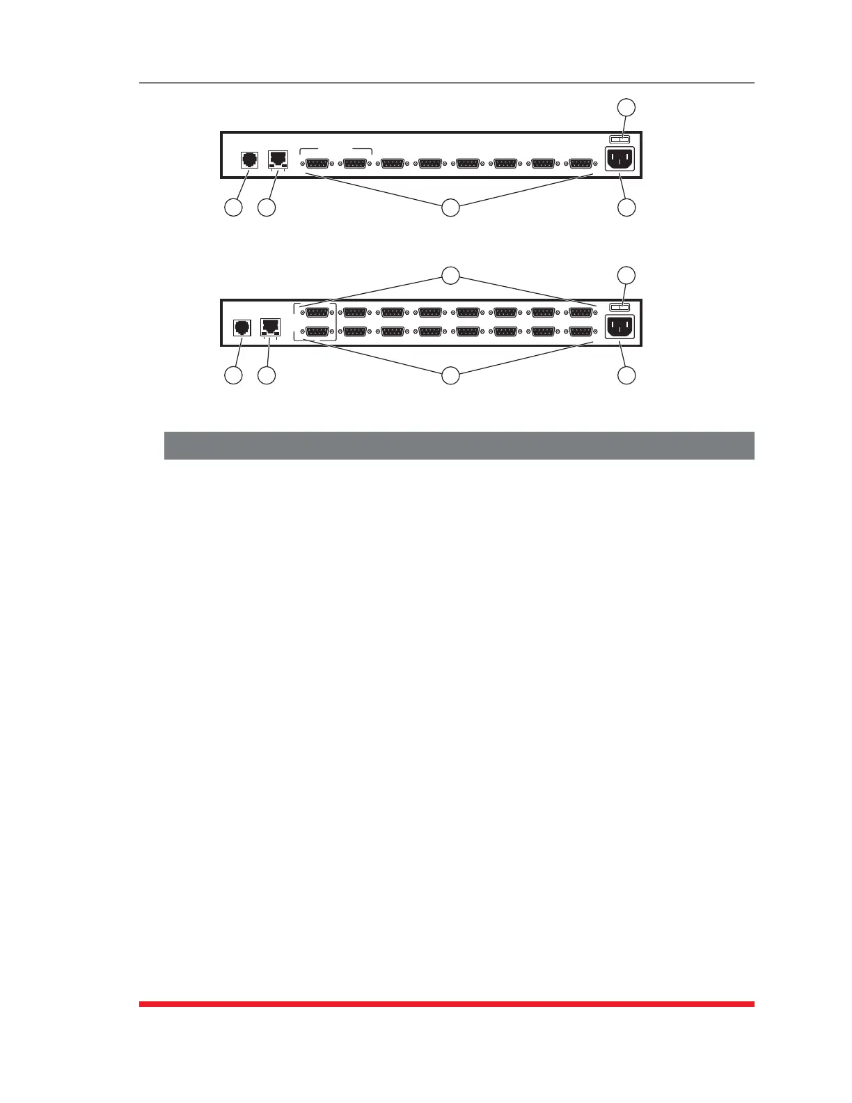
2.5. Back Panel (RSM Series)
As shown in Figures 2.8 and 2.9, the RSM Back Panel includes the following
components:
PhoneLinePort(InternalModemPort): When the Internal Modem is present, the
phone line port is used for connection to your external phone line.
NetworkPort: An RJ45 Ethernet port for connection to your 10/100Base-T,
TCP/IP network. Note that the RSM features a default, IPv4 format IP address
(192.168.168.168). This allows you to connect to the unit without first assigning an
IP address. Note that the Network Port also includes two, small LED indicators for
Link and Data Activity. For more information on Network Port configuration, please
refer to Section 5.9.
RS232SerialPorts: For connection to console ports on target devices. Standard
DB9 connectors configured as DTE ports. The RS232 ports are similar to a serial
port on a PC. When connecting a modem, use a standard serial cable. When
connecting a PC or other DTE device, please refer to Section 4.5 and Appendix B
and Appendix C.
• RSM-8 series units include 8 Serial Ports.
• RSM-16 series units include 16 Serial Ports.
Ã
PowerInlet: An IEC-320-C14 inlet, for connection to your 100 to 240 VAC power
supply. Note that RSM-16DC (-48 VDC powered models) include a terminal block
assembly (see Figure 4.2) in place of the power inlet. For more information, please
refer to Section 4.1.3.
PowerOn/OffSwitch: Master Power Switch
O I
PHONE
LINE
10/100BaseT
LINK
ACTIVITY
SYSTEM SETUP PORTS
(DTE)
1 2 3 4 5 6 7 8
1
2
3
4
5
Figure 2.8: Instrument Back Panel (Model RSM-8)
O I
PHONE
LINE
10/100BaseT
LINK
ACTIVITY
2
1
3
4
5
6
7
8
9
10
11
12
13
14
15
16
SYSTEM
SETUP
PORTS
(DTE)
1
2
3
3
4
5
Figure 2.9: Instrument Back Panel (Model RSM-16)
 Loading...