2-8
Unit Description
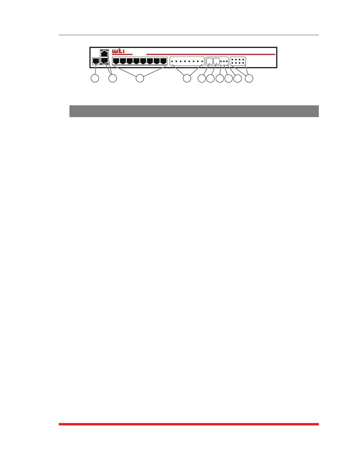
2.7. RSM-8R8-DE Series - Front Panel Components
As shown in Figure 2.11, the RSM-8R8-DE front panel includes the following:
PhoneLinePort(InternalModemPort): When the Internal Modem is present, the
phone line port is used for connection to your external phone line.
NetworkPorts: Two RJ45 Ethernet ports for connection to your primary and
secondary 10Base-T or 100Base-T, TCP/IP networks. Note that Ethernet Port 0
(ETH0) features a default, IPv4 format IP address (192.168.168.168). This allows
you to connect to the unit without first assigning an IP address. The Network Port
also includes two LED indicators for Link and Data Activity. For more information on
port configuration, please refer to Section 5.9.
Notes:
• ThetopNetworkPortisETH0;thebottomNetworkPortisETH1.
• DualEthernetportsareonlyavailableonRSM-8R8-DEseriesunits.Standard
RSM-8R8seriesunitsincludeonlyoneEthernetport.
• WhenconnectingyournetworkcabletoanRSM-8R8-DEseriesunit(Dual
EthernetPorts,)makecertaintoconnecttoPortETH0.
SerialPorts: For connection to console ports on target devices. Standard RJ45
connectors configured as DCE ports. For more information on connecting devices
to the serial ports, please refer to Section 4.5 and Appendix B and Appendix C.
Ã
ACTIVITYLEDs: A series of LEDs, which will light when a CTS signal is detected,
and will flash during data transmission to indicate activity at the corresponding port.
RESETButton: Restarts the RSM-8R4 as described in Section 2.9.
DEFAULTButton: Switches all plugs Off or sets plugs to default values as
described in Section 2.9.
ONIndicator: An LED Indicator which lights when AC Power is applied to
the unit.
RDYIndicator: (Ready) Flashes to indicate that the unit is ready to receive
commands.
DCDIndicator: The Data Carrier Detect indicator.
OutputStatusIndicators: A series of eight LED indicators which light when power
is applied to the corresponding switched outlet.
Note:Providingthatpowerisstillpresentatthesecondarypowerinlet,the
OutputStatusindicatorswillblinkonandoffwhentheprimarypowersourceis
lostordisconnected.
Ethernet
PHONE
ACT LNK
ACT LNK
www.wti.com
RSM-8R8
Remote Site Manager
+
Power Control
SET UP
SERIAL PORTS
1 2 3 4 5 6 7 8
ACTIVITY
1 2 3 4 5 6 7 8
RESET DEFAULT
STATUS
ON RDY DCD
OUTPUT STATUS
1 2 3 4
5 6 7 8
1 2 3 4 5 6 7 8 9 10
Figure 2.11: RSM-8R8-DE Series - Front Panel
 Loading...