7. Tighten:
9 locknut
NOTE:
Lock the adjusting screw so that it does not
move.
8. Install:
9 Cylinder head cover
9. Connect:
9 Fuel hose
10. Install:
9 Spark plug
Locknut:
14 Nm (1.4 m•kg, 10.0 ft•lb)
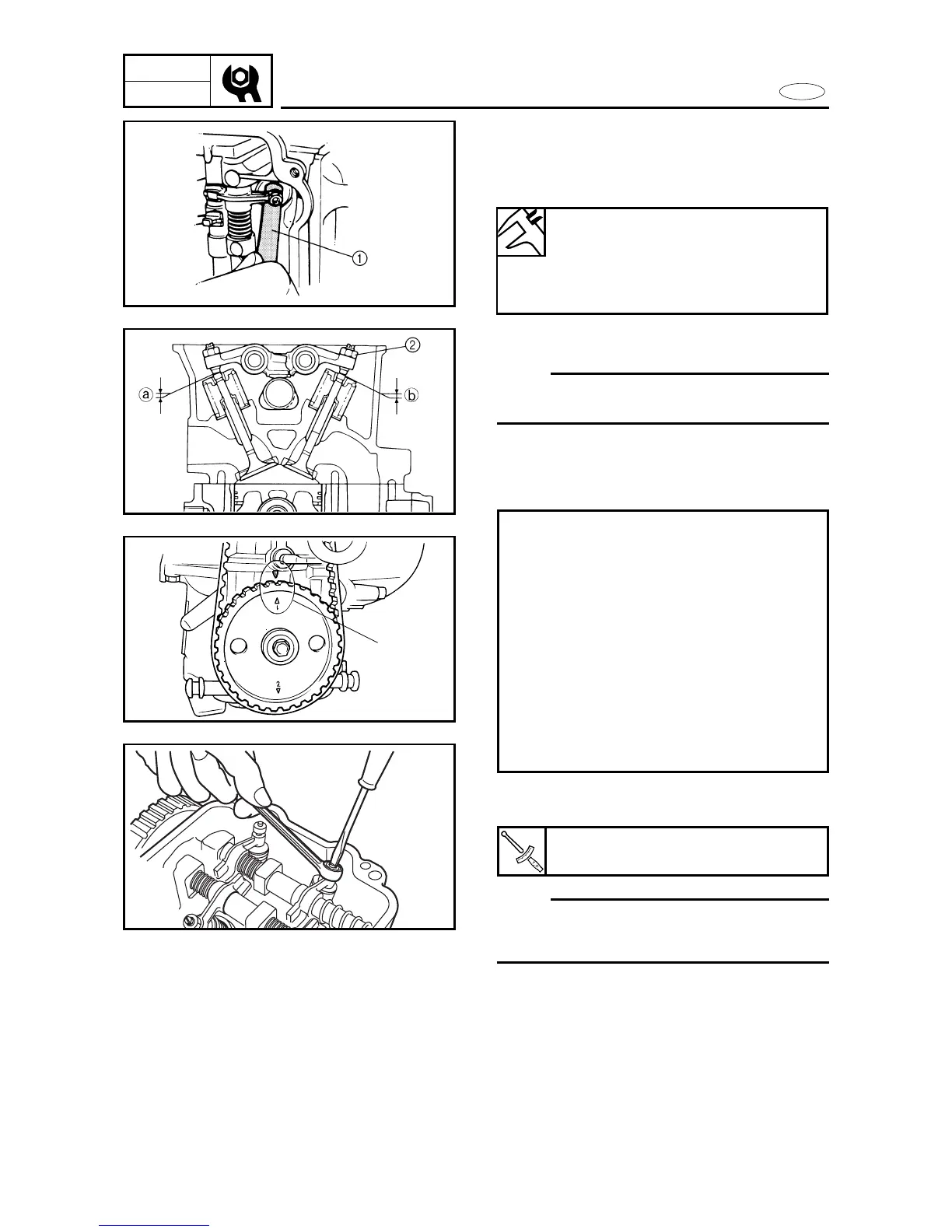
4. Check:
9 Valve clearance
(With a feeler gauge 1)
Out of specification → Adjust.
5. Loosen:
9 locknut
NOTE:
When loosening the lock nut 2, lock the
adjusting screw, so that it does not move.
Adjustment steps:
8 Turn the timing sprocket and align the
“1 and ∆” c on the sprocket with the
“∆” on the cylinder block.
8 Adjust the intake and exhaust valve
clearance for cylinder #1.
8 Turn the timing sprocket 180° (crank-
shaft 360°) and align the “2 and ∆” on
the sprocket with the “∆” on the cylin-
der block.
8 Adjust the intake and exhaust valve
clearance for cylinder #2.
Valve clearance
Intake: 0.20 ± 0.05 mm
(0.008 ± 0.002 in)
Exhaust: 0.25 ± 0.05 mm
(0.010 ± 0.002 in)
6. Adjust:
9 Intake valve clearance a
9 Exhaust valve clearance b