Measuring steps:
cC
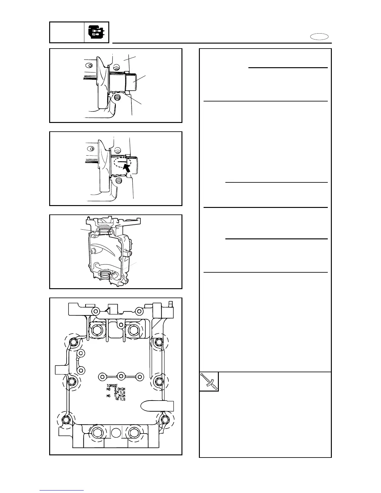
Install the bearings in their original
positions. Incorrect oil clearance mea-
surements can lead to engine damage.
8 Clean the bearings, main journals,
and bearing portions of the crankcase
and cylinder body.
8 Place the cylinder body upside down
on a bench.
8 Install half of the bearings 1 and the
crankshaft 2 into the cylinder body
3.
NOTE:
Align each bearing projection a with
the notch in the cylinder body.
8 Put a piece of Plastigauge
®
on each
main journal.
NOTE:
Do not put the Plastigauge
®
over the oil
holes in the main journal of the crank-
shaft.
8 Install the other half of the bearings
4 into the crankcase.
8 Install the crankcase onto the cylinder
body.
8 Tighten the bolts in the proper
sequence and in two stages.
8 Align each bearing projection b with
the notch in the crankcase.
8 Do not move the crankshaft until the
main-bearing oil clearance measure-
ment has been completed.
5-41
Bolt (M8): (1~4)
1st :15 Nm
(1.5 m•kg, 10.8 ft•lb)
2nd:30 Nm
(3.0 m•kg, 22 ft•lb)
Bolt (M6): (5~10)
1st :6 Nm
(0.6 m•kg, 4.5 ft•lb)
2nd:12 Nm
(1.2 m•kg, 8.7 ft•lb)