5.2 Servomotor Main Circuit Wire Size and Connectors
5-21
5
(b) Brake Power Supply Connectors
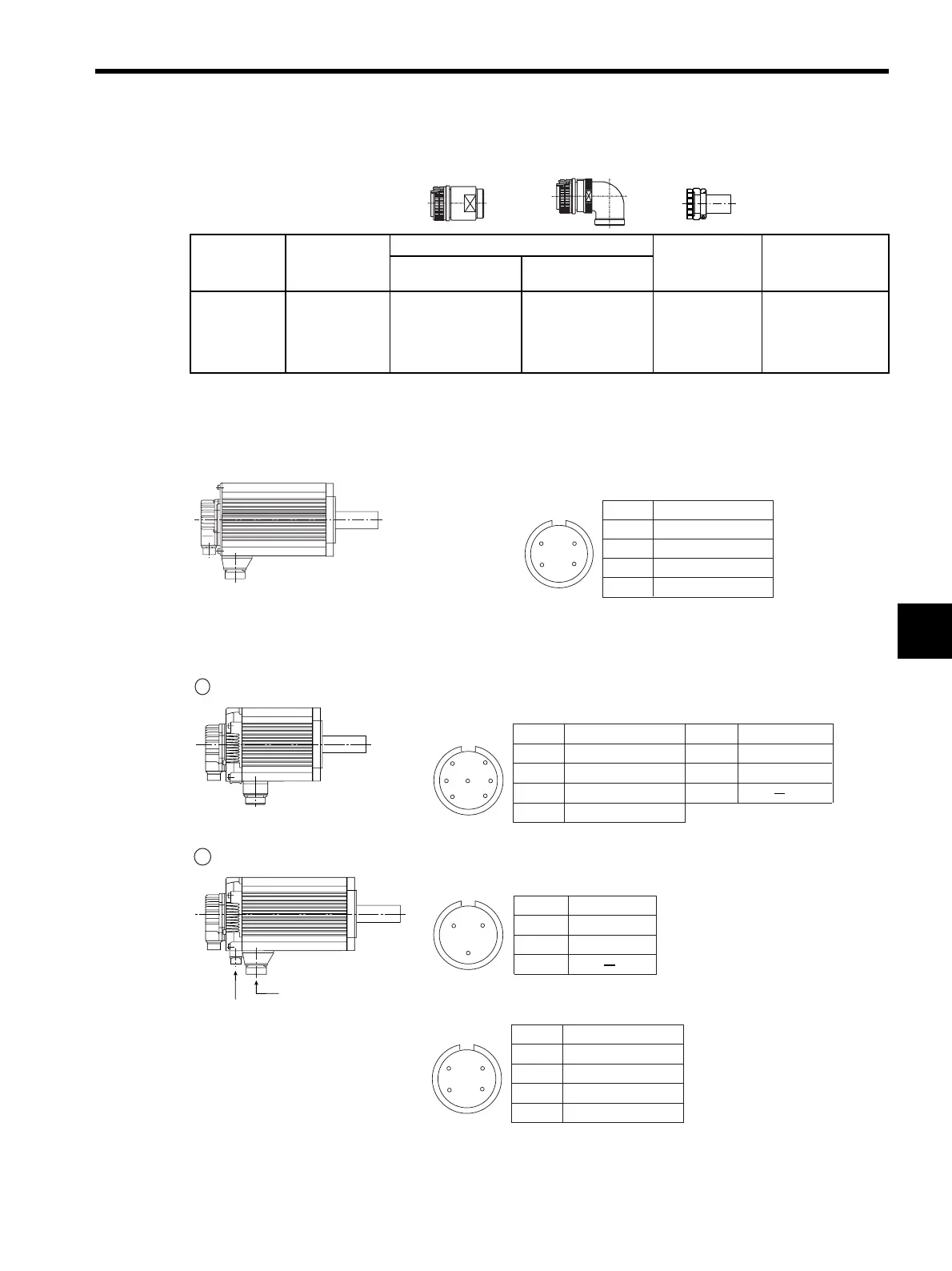
(5) Servomotor Main Circuit Connector Pin Arrangement
(a) Servomotors Without Holding Brakes
(b) Servomotors With Holding Brakes
Capacity
(kW)
Connector on
Servomotor
Plug
Cable Clamp
Applicable Cable
Range in mm (in)
(For reference)
Straight L-shaped
5.5
7.5
11.0
15.0
CE05-2A10SL-
3PC-B
CE05-6A10SL-3SC-
B-BSS
CE05-8A10SL-3SC-
B-BAS
CE3057-4A-1
φ 3.6 (φ0.14) to φ5.6
(φ0.22)
0.45 to 15.0 kW
Servomotor-end
connector
Servomotor Connector Pin Arrangement
A
B
C
D
Phase U
Phase V
Phase W
FG (Frame Ground)
D
BC
A
Pin No. Signal
1 0.45 to 4.4 kW
2 5.5 to 15.0 kW
Servomotor-end
connector
Servomotor-end connector
Brake-end connector
Brake Connector Pin Arrangement
B
C
A
Servomotor Connector Pin Arrangement
Servomotor Connector Pin Arrangement
D
B
G
C
AF
E
A
B
C
D
Phase U
Phase V
Phase W
FG (Frame Ground)
Pin No. Signal
E *
F *
G
Brake terminal
Brake terminal
Pin No. Signal
A
B
C
D
Phase U
Phase V
Phase W
FG (Frame Ground)
D
BC
A
Pin No. Signal
A *
B *
C
Brake terminal
Brake terminal
Pin No. Signal
* No polarity
* No polarity
Artisan Technology Group - Quality Instrumentation ... Guaranteed | (888) 88-SOURCE | www.artisantg.com
 Loading...


