8.1 Trial Operation
8-13
8
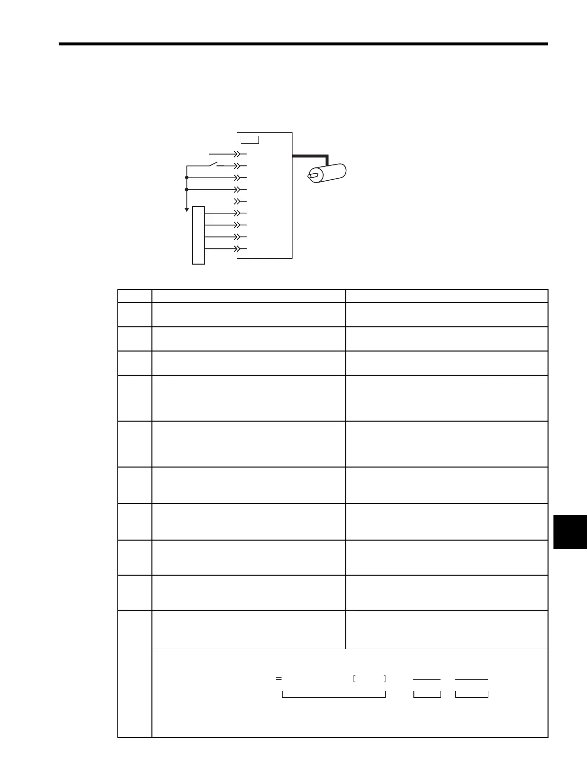
(3) Operating Procedure in Position Control Mode (Pn000 = n.1)
The following circuit is required: External input signal circuit or equivalent.
Step Description Check Method and Remarks
1 Match the reference pulse form with the pulse out-
put form from the host controller.
Set the reference pulse with Pn200=n.×. Refer
to 8.6.1 (2) Setting a Reference Pulse Form.
2 Set the reference unit and electronic gear ration so
that it coincides with the host controller setting.
Set the electronic gear ratio with Pn202/Pn203. Refer
to 8.6.2 Setting the Electronic Gear.
3 Turn ON the power and the servo ON (/S-ON) input
signal.
−
4 Send the pulse reference for the number of motor
rotation easy to check (for example, one motor revo-
lution) and with slow speed from the host controller
in advance.
Set the motor speed of several 100 min
-1
for the refer-
ence pulse speed because such speed is safe.
5 Check the number of reference pulses input to the
SERVOPACK by the changed amount before and
after the Un00C (input reference pulse counter)
[pulse] was executed.
Refer to 7.1.3 Basic Mode Selection and Operation for
how it is displayed.
Un00C (input reference pulse counter) [pulse]
6 Check the actual number of motor rotation [pulse]
by the changed amount before and after the Un003
(rotation angle 1) [pulse] was executed.
Refer to 7.1.3 Basic Mode Selection and Operation for
how it is displayed.
Un003 (rotation angle 1) [pulse]
7 Check that steps 5 and 6 satisfy the following equa-
tion:
Un003=Un00C × (Pn202/Pn203)
−
8 Check that the motor rotation direction is the same
as the reference.
Check the input pulse polarity and input reference
pulse form. Refer to 8.6.1 (2) Setting a Reference
Pulse Form.
9 Input the pulse reference with the large number of
motor rotation from the host controller to obtain the
constant speed.
Set the motor speed of several 100 min
-1
for the refer-
ence pulse speed because such speed is safe.
10 Check the reference pulse speed input to the SER-
VOPACK using the Un007 (input reference pulse
speed) [min
-1
].
Refer to 7.1.3 Basic Mode Selection and Operation for
how it is displayed.
Un007 (input reference pulse speed) [min
-1
]
The number of input reference pulses (Un00C) can be obtained from the following equation.
* The encoder pulse differs depending on the model of the servomotor used.
Pulse reference
SERVOPACK
Reference pulse
according to
parameter
Pn200.0 setting
+24V
/S-ON
P-OT
N-OT
CLR
∗
∗
Do not connect the CLR signal.
PULS
/PULS
40
47
42
43
7
8
SIGN
/SIGN
11
12
15
CN1
Un007(input reference pulse speed) input reference pulse pulses/S × 60 ×
Pn203
Pn202
1
2 (8192)
13
×
Reference input ppm Electronic
gear ratio
Encoder
pulse
∗
Artisan Technology Group - Quality Instrumentation ... Guaranteed | (888) 88-SOURCE | www.artisantg.com
 Loading...


