8.7 Operating Using Torque Control
8-65
8
(2) Internal Speed Limit Function
(3) External Speed Limit Function
The Principle of Speed Limiting
When the speed is outside of the allowable range, a torque that is proportional to the difference between the actual speed
and the speed limit is used as negative feedback to bring the speed back within the speed limit range. Accordingly, there is
a margin generated by the load conditions in the actual motor speed limit value.
(4) Signals Output during Servomotor Speed Limit
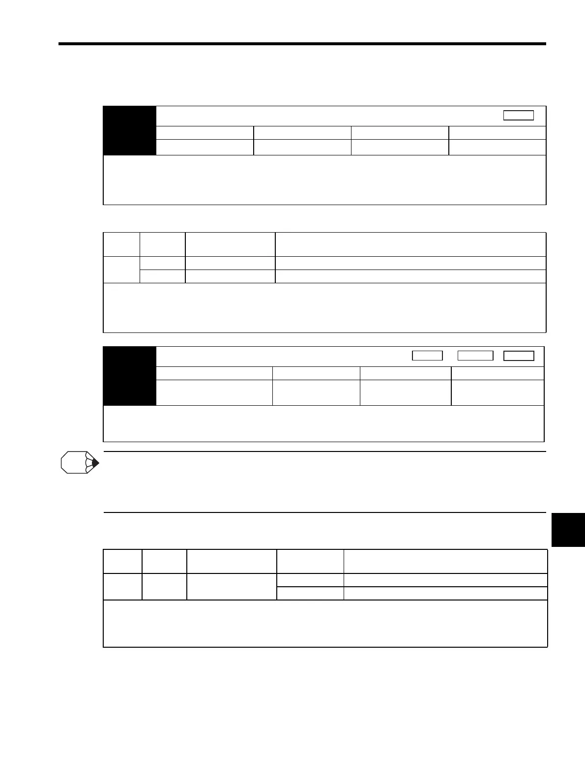
Pn407 Speed Limit During Torque Control
Setting Range Setting Unit Factory Setting Setting Validation
0 to 10000
min
-1
10000 Immediately
Sets the servomotor speed limit value during torque control.
The setting in this parameter is enabled when Pn002 = n.
0.
The servomotor’s maximum speed will be used when the setting in this parameter exceeds the maximum speed of the ser-
vomotor used.
Type Signal
Name
Connector
Pin Number
Name
Input V-REF CN1-5 External Speed Limit Input
SG CN1-6 Signal Ground
Inputs an analog voltage reference as the servomotor speed limit value during torque control.
The smaller value is enabled, the speed limit input from V-REF or the Pn407 (Speed Limit during Torque Control) when
Pn002 = n.
1.
The setting in Pn300 determines the voltage level to be input as the limit value. Polarity has no effect.
Torque
Pn300 Speed Reference Input Gain
Setting Range Setting Unit Factory Setting Setting Validation
150 to 3000
(1.50 to 30.0 V/rated speed)
0.01 V/rated speed 600
(6.00 V/rated speed)
Immediately
Sets the voltage level for the speed that is to be externally limited during torque control.
With Pn300 = 600 (factory setting) and 6 V input from V-REF (CN1-5, 6), the actual motor speed is limited to the rated
speed of the servomotor used.
Speed
Position
Torque
INFO
Type Signal
Name
Connector
Pin Number
Setting Meaning
Output /VLT Must be allocated
CN1-
ON (low level) Servomotor speed limit being applied.
OFF (high level) Servomotor speed limit not being applied.
This signal is output when the servomotor speed reaches the speed limit value set in Pn407 or set by the analog voltage ref-
erence.
For use, this output signal must be allocated with parameter Pn50F. For details, refer to 7.3.3 Output Circuit Signal Alloca-
tion.
Artisan Technology Group - Quality Instrumentation ... Guaranteed | (888) 88-SOURCE | www.artisantg.com
 Loading...


