154
ABOV Semiconductor Co., Ltd.
11.5 Timer 0/1/2
11.5.1 Overview
The 8-bit timer 0/1/2 consists of multiplexer, timer 0/1/2 counter register, timer 0/1/2 data register, timer 0/1/2 capture
data register and timer 0/1/2 control register (TnCNT, TnDR, TnCDR, TnCR).
It has three operating modes:
− 8-bit timer/counter mode
− 8-bit PWM output mode
− 8-bit capture mode
The timer/counter 0/1/2 can be clocked by an internal or an external clock source (ECn). The clock source is selected
by clock selection logic which is controlled by the clock selection bits (TnCK[2:0]).
− TIMER 0/1/2 clock source: f
X
/2, 4, 8, 32, 128, 512, 2048 and ECn
In the capture mode, by EINT1n, the data is captured into input capture data register (TnCDR). In timer/counter mode,
whenever counter value is equal to TnDR, TnO port toggles. Also the timer 0/1/2 outputs PWM waveform through
PWMnO port in the PWM mode.
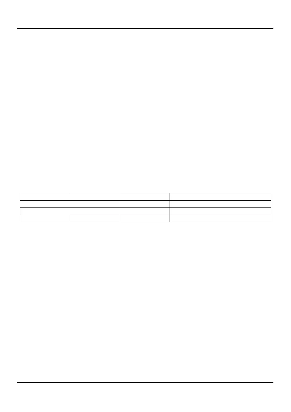
Table 11-5 Timer 0/1/2 Operating Modes