239
ABOV Semiconductor Co., Ltd.
11.12.4 Data format
A serial frame is defined to be one character of data bits with synchronization bits (start and stop bits) and optionally a
parity bit for error detection.
The UART2/3/4 supports all 30 combinations of the following as valid frame formats.
− 1 start bit
− 5, 6, 7, 8 or 9 data bits
− no, even or odd parity bit
− 1 or 2 stop bits
A frame starts with the start bit followed by the least significant data bit (LSB). Then the next data bits, up to nine, are
succeeding, ending with the most significant bit (MSB). If parity function is enabled, the parity bit is inserted between
the last data bit and the stop bit. A high-to-low transition on data pin is considered as start bit. When a complete frame
is transmitted, it can be directly followed by a new frame or the communication line can be set to an idle state. The idle
means high state of data pin. The following figure shows the possible combinations of the frame formats. Bits inside
brackets are optional.
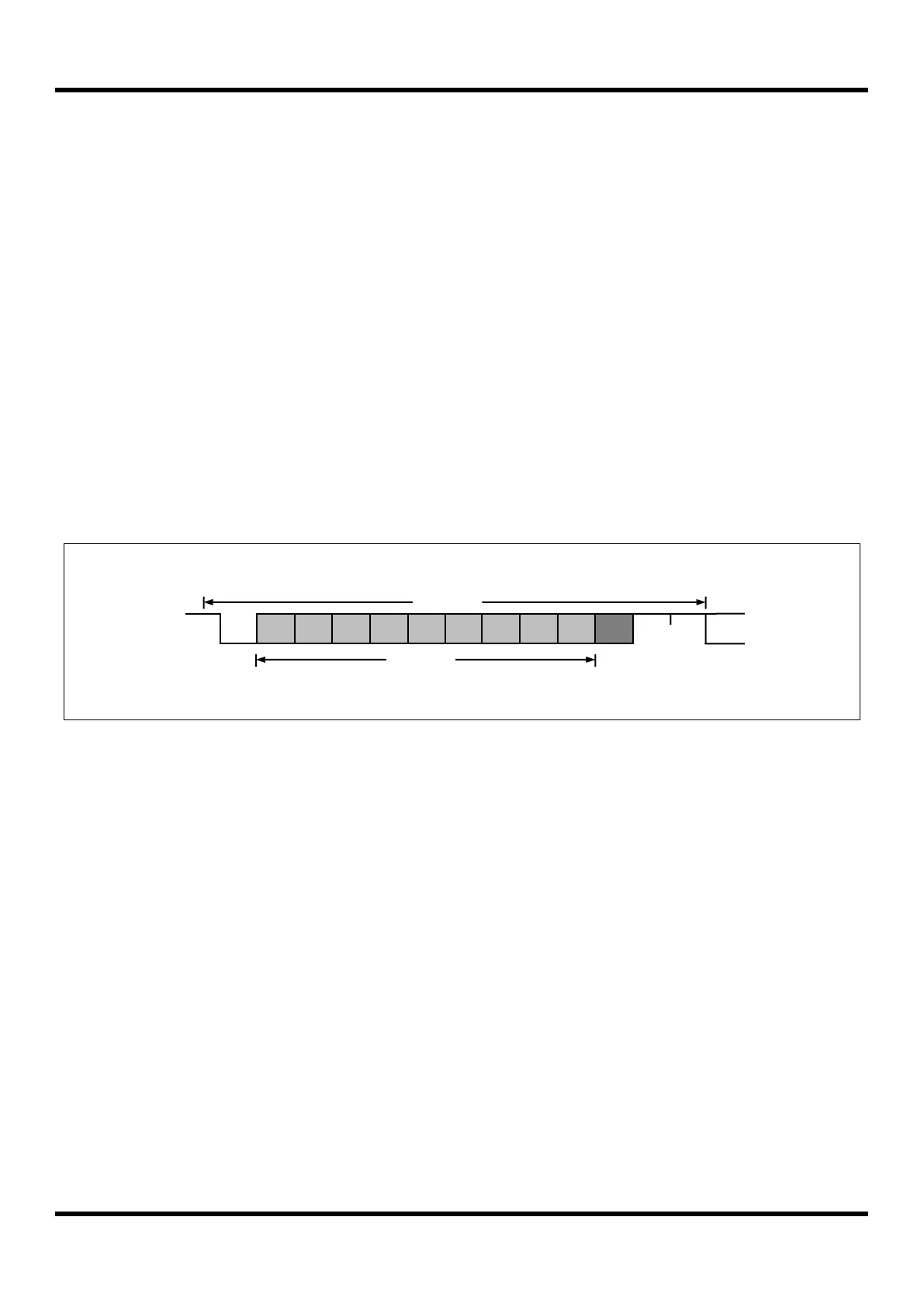
Figure 11.58 Frame Format
1 data frame consists of the following bits
• Idle No communication on communication line (TxD/RxD)
• St Start bit (Low)
• Dn Data bits (0~8)
• Parity bit ------------ Even parity, Odd parity, No parity
• Stop bit(s) ---------- 1 bit or 2 bits
The frame format used by the UART2/3/4 is set by the UnSIZE[2:0], UnPM[1:0] and USBSn bits in UARTnCR1 and
UARTnCR3 register. The Transmitter and Receiver use the same setting.