165
ABOV Semiconductor Co., Ltd.
11.6 Timer 3/4/5/6
11.6.1 Overview
The 16-bit timer 3/4/5/6 consists of multiplexer, timer 3/4/5/6 A data register high/low, timer 3/4/5/6 B data register
high/low and timer 3/4/5/6 control register high/low (TnADRH, TnADRL, TnBDRH, TnBDRL, TnCRH, TnCRL).
It has four operating modes:
− 16-bit timer/counter mode
− 16-bit capture mode
− 16-bit PPG output mode (one-shot mode)
− 16-bit PPG output mode (repeat mode)
The timer/counter 3/4/5/6 can be clocked by an internal or an external clock source (ECn). The clock source is
selected by clock selection logic which is controlled by the clock selection bits (TnCK[2:0]).
− TIMER 3/4/5/6 clock source: f
X
/1, 2, 4, 8, 32, 128, 512 and ECn
In the capture mode, by EINT1n, the data is captured into input capture data register (TnBDRH/TnBDRL). Timer
3/4/5/6 outputs the comparision result between counter and data register through TnO port in timer/counter mode. Also
Timer 3/4/5/6 outputs PWM wave form through PWMnO port in the PPG mode.
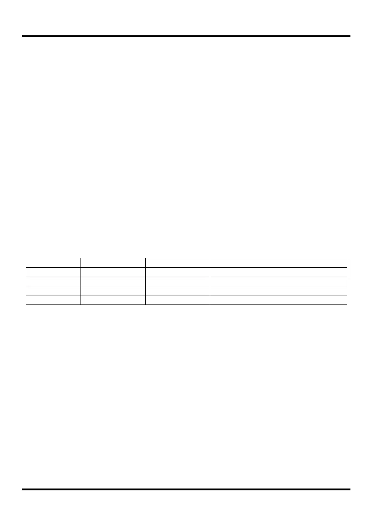
16 Bit Timer/Counter Mode
16 Bit PPG Mode (one-shot mode)
16 Bit PPG Mode (repeat mode)
Table 11-7 Timer 3/4/5/6 Operating Modes
11.6.2 16-Bit Timer/Counter Mode
The 16-bit timer/counter mode is selected by control register as shown in Figure 11.15.
The 16-bit timer have counter and data register. The counter register is increased by internal or external clock input.
Timer 3/4/5/6 can use the input clock with one of 1, 2, 4, 8, 32, 128 and 512 prescaler division rates (TnCK[2:0]).
When the value of TnCNTH, TnCNTL and the value of TnADRH, TnADRL are identical in Timer 3/4/5/6 respectively, a
match signal is generated and the interrupt of Timer 3/4/5/6 occurs. The TnCNTH, TnCNTL value is automatically
cleared by match signal. It can be also cleared by software (TnCC).
The external clock (ECn) counts up the timer at the rising edge. If the ECn is selected as a clock source by TnCK[2:0],
EC3/EC4/EC5/EC6 port should be set to the input port by P26IO/P27IO/P14IO/P15IO bit.