209
ABOV Semiconductor Co., Ltd.
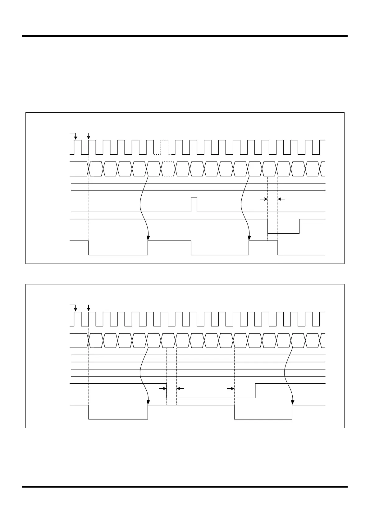
11.8.5 10-Bit PWM Repeat Mode
The 10-bit PWM repeat mode is selected by PWMMD[1:0] bits set to “1xb”. A 10-bit counter register is increased by
internal clock input on operation. When the PWMCNTH/PWMCNTL is identical to the PWMADRH/PWMADRL, a
match signal is generated, the PWMOUT pin is inverted and the counting is continued to “3FFH”. If the counter
reaches “3FFH” , the counter will be cleared to “000H” and the 10-bit PWM generator will be restarted.
X 1 2 4 1 2 4 5 1 2
PWM clock
Counter
PWMADRH/L
PWM Interrupt
PWMOUT
Match
- PWMOUT signal without delay: "Start Low" (PWMPOL = 1b) and without delay (TRIGRS = 10b)
Set PWMEN
0
Clear and Start
3 0
4
Match
30
TRIG Input
3FF
0 < Tst < 2/fpwm
Tst
Figure 11.43 Timing Chart of 10-bit PWM Repeat Mode Without Delay
X 1 2 4 8 9 1 2 4 5
PWM clock
Counter
PWMADRH/L
PWMOUT
Match
- PWMOUT signal with delay: "Start Low" (PWMPOL = 1b) and with delay (TRIGRS = 11b)
Set PWMEN
0
Clear and Start
3 3
4
Match
07
TRIG Input
6
Tst
5
PWMDLYDR
3
Delay Time
(PWMDLYDR+1)/fpwm
Figure 11.44 Timing Chart of 10-bit PWM Repeat Mode With Delay