277
ABOV Semiconductor Co., Ltd.
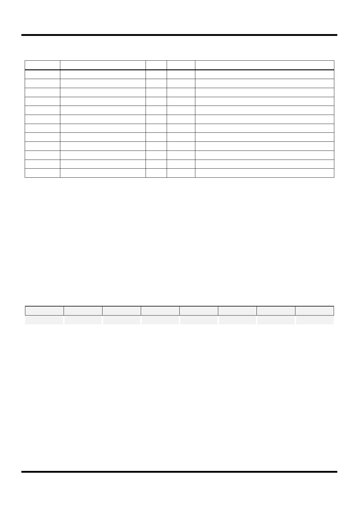
11.13.35 Register Map
USIn Baud Rate Generation Register
USIn SDA Hold Time Register
USIn SCL Low Period Register
USIn SCL High Period Register
USIn Slave Address Register
Table 11-24 USI0/1 Register Map (where n = 0 and 1)
11.13.36 Register Description
USI0/1 module consists of USI0/1 baud rate generation register (USInBD), USI0/1 data register (USInDR), USI0/1
SDA hold time register (USInSDHR), USI0/1 SCL high period register (USInSCHR), USI0/1 SCL low period Register
(USInSCLR), USI0/1 slave address register (USInSAR), USI0/1 control register 1/2/3/4 (USInCR1/2/3/4), USI0/1
status register 1/2 (USInST1/2).
11.13.37 Register Description for USI0/1
USInBD (USI0/1 Baud- Rate Generation Register: For UART and SPI mode) : 403AH/404AH (XSFR),
n = 0 and 1
Initial value : FFH
The value in this register is used to generate internal baud rate in asynchronous
mode or to generate SCKn clock in SPI mode. To prevent malfunction, do not write ‘0’
in asynchronous mode and do not write ‘0’ or ‘1’ in SPI mode.
NOTE)
1. In common with USInSAR register, USInBD register is
used for slave address register when the USI0/1 I2C mode.