178
ABOV Semiconductor Co., Ltd.
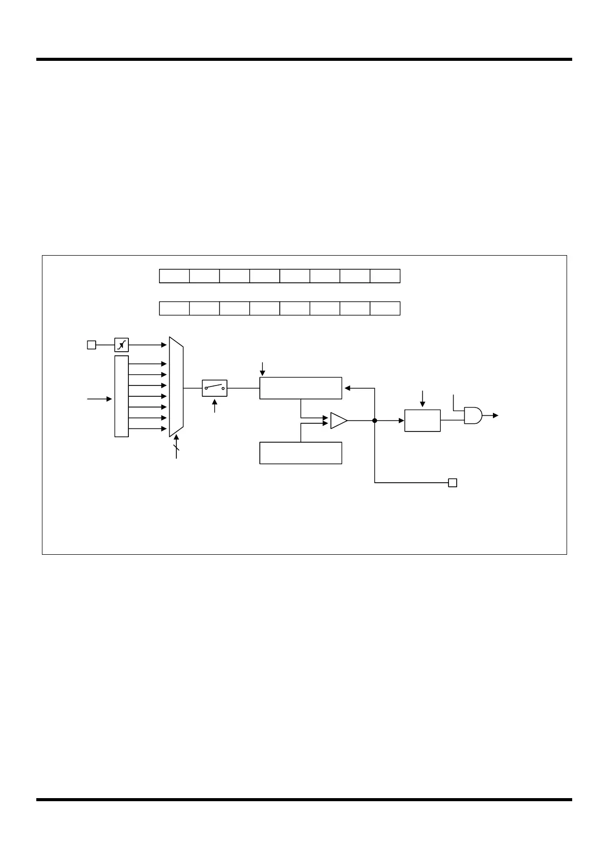
11.7.3 16-Bit Timer/Counter 7 Mode
The 16-bit timer/counter mode is selected by control register as shown in Figure 11.24.
The 16-bit timer have counter and data register. The counter register is increased by internal or external clock input.
Timer 7 can use the input clock with one of 2, 4, 8, 32, 128, 512 and 2048 prescaler division rates (T7CK[2:0]).
A 16-bit timer/counter register T7CNT, T8CNT are incremented from 0000H to FFFFH until it matches T7DR, T8DR
and then cleared to 0000H. The match signal output generates the Timer 7 Interrupt (No timer 8 interrupt). The clock
source is selected from T7CK[2:0] and 16BIT bit must be set to ‘1’. Timer 7 is LSB 8-bit, the timer 8 is MSB 8-bit.
The external clock (EC7) counts up the timer at the rising edge. f the EC7 is selected as a clock source by T7CK[2:0],
EC7 port should be set to the input port by P63IO bit.
P
r
e
s
c
a
l
e
r
fx
M
U
X
fx/2
T8CNT/T7 CNT (16Bit)
EC7
fx/4
fx/8
fx/32
fx/128
fx/512
fx/2048
3
T7CK[2:0]
T7CN
16- bit Timer 7 Counter
T8DR/T7 DR (16Bit)
Comparator
T7IFR
T7O
16- bit Timer 7 Data Register
S/W
Clear
Clear
Match
T7ST
MSB LSB
MSB LSB
T7EN
T7CR
1
T7IE
T7MS T7CK2 T7CK1 T7CK0 T7CN T7ST
X
0 X X X X X
16BIT
T8CR
1
T8MS T8CN T8ST T8CK3 T8CK2 T8CK1 T8CK0
0 X X
1
1 1 1
To interrupt
block
T7IE
ADDRESS : 4090H (XSFR)
INITIAL VALUE : 0000_0000B
INITIAL VALUE : 0000_0000B
ADDRESS : 4092H (XSFR)
NOTE)
1. The T8CR.7 bit (16BIT) should be set to ‘1’ and the T8CK[3:0] should be set to “1111b”.
2. Do not set to “0000b” in the T8CK[3:0], when fx is over 10MHz.
Figure 11.24 16-Bit Timer/Counter Mode for Timer 7