156
ABOV Semiconductor Co., Ltd.
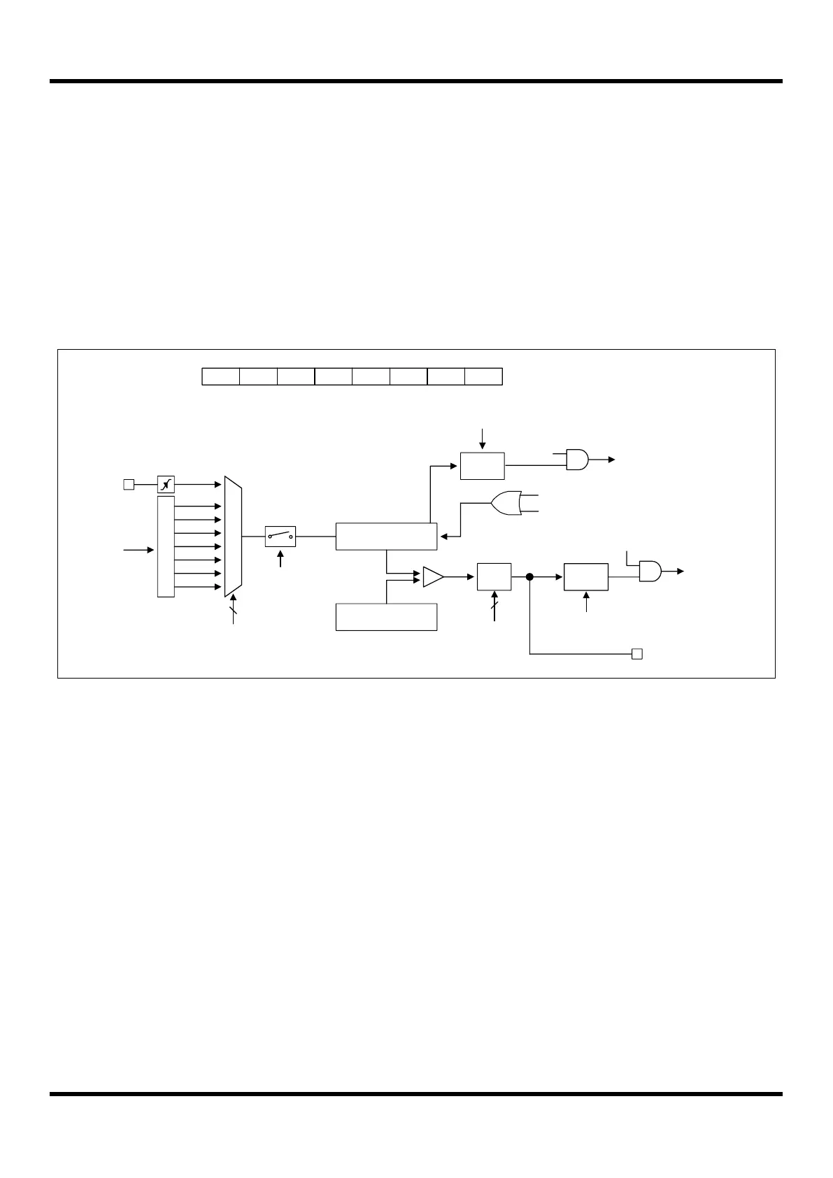
11.5.3 8-Bit PWM Mode
The timer 0/1/2 has a high speed PWM (Pulse Width Modulation) function. In PWM mode, TnO/PWMnO pin outputs
up to 8-bit resolution PWM output. This pin should be configured as a PWM output by setting the T0O/PWM0O,
T1O/PWM1O and T2O/PWM2O function by P4FSRL[4:3], P4FSRH[1:0] and P4FSRH[3:2] bits. In the 8-bit
timer/counter mode, a match signal is generated when the counter value is identical to the value of TnDR. When the
value of TnCNT and TnDR is identical in timer n, a match signal is generated and the interrupt of timer 0/1/2 occurs. In
PWM mode, the match signal does not clear the counter. Instead, it runs continuously, overflowing at “FFH” and then
continues incrementing from “00H”. The timer 0/1/2 overflow interrupt is generated whenever a counter overflow
occurs. TnCNT value is cleared by software (TnCC) bit.
P
r
e
s
c
a
l
e
r
fx
M
U
X
fx/2
TnCNT(8Bit)
ECn
fx/4
fx/8
fx/32
fx/128
fx/512
fx/2048
3
TnCK[2:0]
TnEN
8-bit Timer n Counter
TnDR(8Bit)
Comparator
TnO/PWMnO
8-bit Timer n Data Register
Clear
Match
MUX
TnOVIFR
Clear
TnMS[1:0]
2
S/W
TnEN - TnMS1 TnMS0 TnCK2 TnCK1 TnCK0 TnCCTnCR
1 - 0 1 x x x x
ADDRESS : D2H/DAH/DDH
INITIAL VALUE: 0000_0000B
Match signal
TnCC
TnIFR
To interrupt
block
TnOVIE
To interrupt
block
TnMIE
S/W
Clear
Figure 11.9 8-Bit PWM Mode for Timer 0/1/2 (Where n = 0, 1 and 2)