EasyManuals Logo

Abov MC97F60128 User Manual

Abov MC97F60128
382 pages
To Next Page IconTo Next Page
To Previous Page IconTo Previous Page
Page #238 background imageLoading...
Page #238 background image
238
MC97F60128
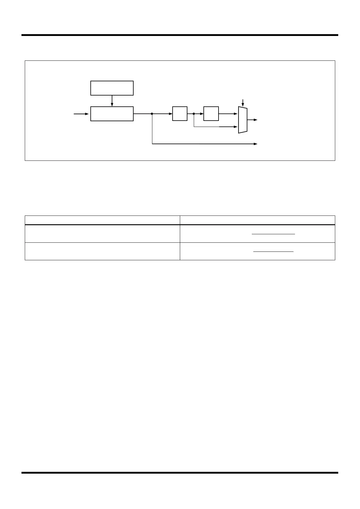
11.12.3 Clock Generation
Figure 11.57 Clock Generation Block Diagram (where n = 2,3 and 4)
The clock generation logic generates the base clock for the transmitter and receiver.
Following table shows equations for calculating the baud rate (in bps).
Operating Mode
Equation for Calculating Baud Rate
Normal Mode(U2Xn=0)
Baud Rate =
fx
16(UARTnBD + 1)
Double Speed Mode(U2Xn=1)
Baud Rate =
fx
8(UARTnBD + 1)
Table 11-19 Equations for Calculating Baud Rate Register Setting(where n = 2,3 and 4)
Baud Rate
Generator
UARTnBD
/2
/8
SCLK
f
SCLK
(UARTnBD+1
)
rxclk
M
U
X
U2Xn
txclk

Table of Contents

Questions and Answers:

Question and Answer IconNeed help?

Do you have a question about the Abov MC97F60128 and is the answer not in the manual?

Abov MC97F60128 Specifications

General IconGeneral
BrandAbov
ModelMC97F60128
CategoryMicrocontrollers
LanguageEnglish

Related product manuals