NOTE)
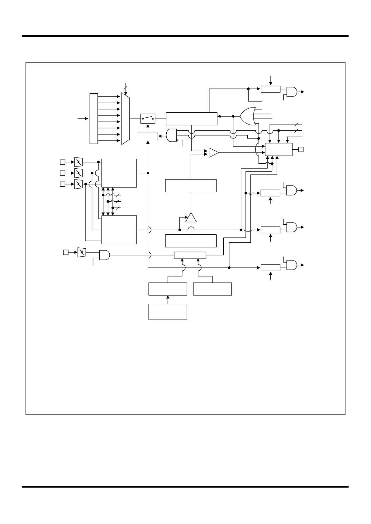
1. The PWMEN bit is automatically cleared to “0b” after an overflow of the 10-bit counter
occurs at a PWM one-shot mode.
2. The PWMEN bit is set to “1b” by a falling edge trigger of the external TRIG pin when it is
a PWM one-shot mode with auto-enable and the EMGIFR bit is set to “0b”.
3. The noise filter controller has a timer to realize an invalid trigger signal. The timer will be
cleared and restarted every the new cycle of the PWM generator.
4. The noise filter controller doesn’t work if the noise filter data register (NFILDR) is “00H”.
5. If a shot stop occurs by a falling edge trigger of the selected pin, the PWMOUT pin goes to
low/high level according to PWMPOL = “0b”/”1b” during the remaining current PWM cycle,
respectively. After that, the next PWM cycle starts with the PWMBDR.