186
ABOV Semiconductor Co., Ltd.
Update period & duty register value at once
The period and duty of PWM comes to move from temporary registers to T8PPRH/L (PWM Period Register) and
T8ADRH/L,T8BDRH/L,T8CDRH/L (PWM Duty Register) when always period match occurs. If you want that the period
and duty is immediately changed, the UPDT bit in the T8PCR1 register must set to ‘1’. It should be noted that it needs
the 3 cycle of timer clock for data transfer in the internal clock synchronization circuit. So the update data is written
before 3 cycle of timer clock to get the right output waveform.
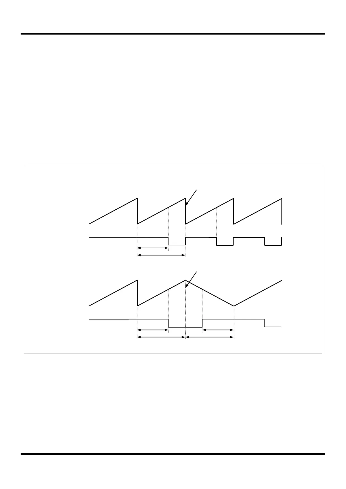
Phase correction & Frequency correction
On operating PWM, it is possible that it is changed the phase and the frequency by using BMOD bit (back-to-back
mode) in T8PCR1 register. (Figure 11.31, Figure 11.32, Figure 11.33 referred)
In the back-to-back mode, the counter of PWM repeats up/down count. In fact, the effective duty and period becomes
twofold of the register set values. (Figure 11.32, Figure 11.33 referred)
Figure 11.31 Example of PWM Output Waveform

 Loading...
