194
ABOV Semiconductor Co., Ltd.
P
r
e
s
c
a
l
e
r
fx
M
U
X
fx/2
T8CNT/T7CNT (16Bit)
EC7
fx/4
fx/8
fx/32
fx/128
fx/512
fx/2048
3
T7CK[2:0]
T7CN
16-bit Timer 7 Counter
T8DR/T7DR (16Bit)
Comparator
T7O
16-bit Timer 7 Data Register
Clear
Match
T8CAPR/T7CAPR (16Bit)
Clear
EINT17
EIPOL2H[7:6]
FLAG17
(EIFLAG2.7)
S/W
Clear
To interrupt
block
2
T7MS
T7ST
16-bit Timer 7 Capture Register
MSB LSB
MSB LSB
MSB LSB
T7IFR
To interrupt
block
T7IE
S/W
Clear
NOTE)
1. The T8CR.7 bit (16BIT) should be set to ‘1’ and the T8CK[3:0] should be set to “1111b”.
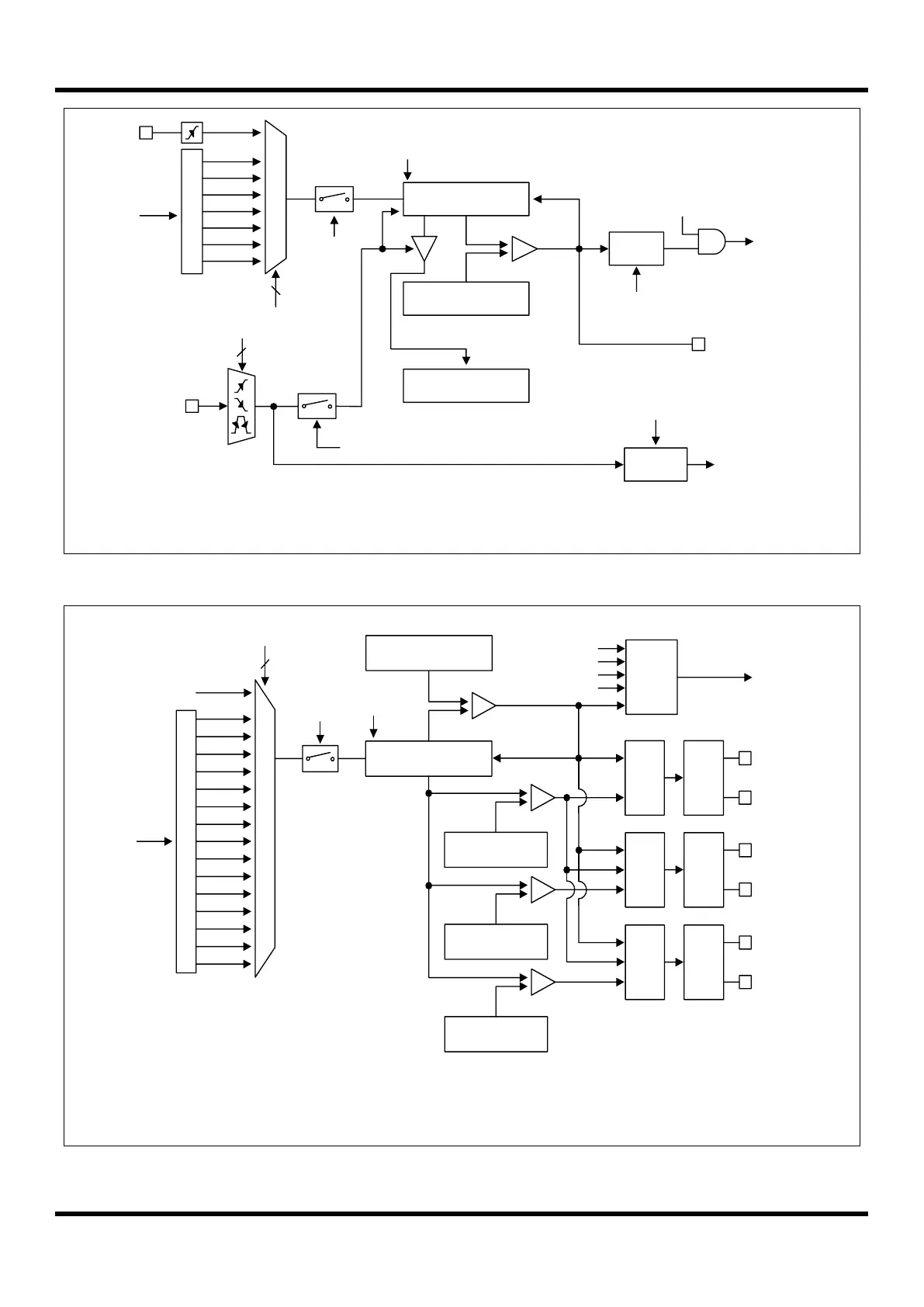
Figure 11.39 16-Bit Timer 7 Block Diagram
P
r
e
s
c
a
l
e
r
fx
M
U
X
fx/2
fx/4
fx/16
fx/32
fx/64
fx/8
fx/1
Comparator
10-bit Counter
2Bit + T8CNT
10-bit A Data Register
T8ADRH/T8ADRL
Control
Up/Down
Comparator
T8PPRH/T8PPRL (10Bit)
Period Match
PWM
Output
Control
A-ch
PWM8AA
T8CN
4
T8CK[3:0]
T7 Clock Source
fx/128
fx/256
fx/1024
fx/2048
fx/4096
fx/512
fx/8192
fx/16384
Timer 8 PWM Period Register
T8ST
PWM
Delay
Control
A-ch
PWM8AB
Comparator
10-bit B Data Register
T8BDRH/T8BDRL
PWM
Output
Control
B-ch
PWM8BA
PWM
Delay
Control
B-ch
PWM8BB
Comparator
10-bit C Data Register
T8CDRH/T8CDRL
PWM
Output
Control
C-ch
PWM8CA
PWM
Delay
Control
C-ch
PWM8CB
A Match
B Match
C Match
Interrupt
Generator
A Match
B Match
C Match
Bottom (Underflow)
To interrupt
block
NOTE)
1. Do not set to “1111b” in the T8CK[3:0], when two 8-bit timer 7/8 modes.
2. Do not set to “0000b” in the T8CK[3:0], when fx is over 10MHz
Figure 11.40 10-Bit PWM Timer 8 Block Diagram