68 4 Tool Table
4.1 Tool Table
4.1 Tool Table
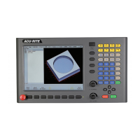
Overview
When the MILLPWR
G2
runs a program step that activates a tool, it
only activates the diameter, and length values on that row of the Tool
Table. The tool number, or tool type are not activated in dialogues that
have these fields.
Tool Table values are automatically converted to their inch or
millimeter equivalents when the MILLPWR
G2
mode is changed. All
typed values must match the current unit mode of the MILLPWR
G2
.
Define and store up to 99 tools on the tool table. Type of data stored
on the Tool Table is information specific to each tool.
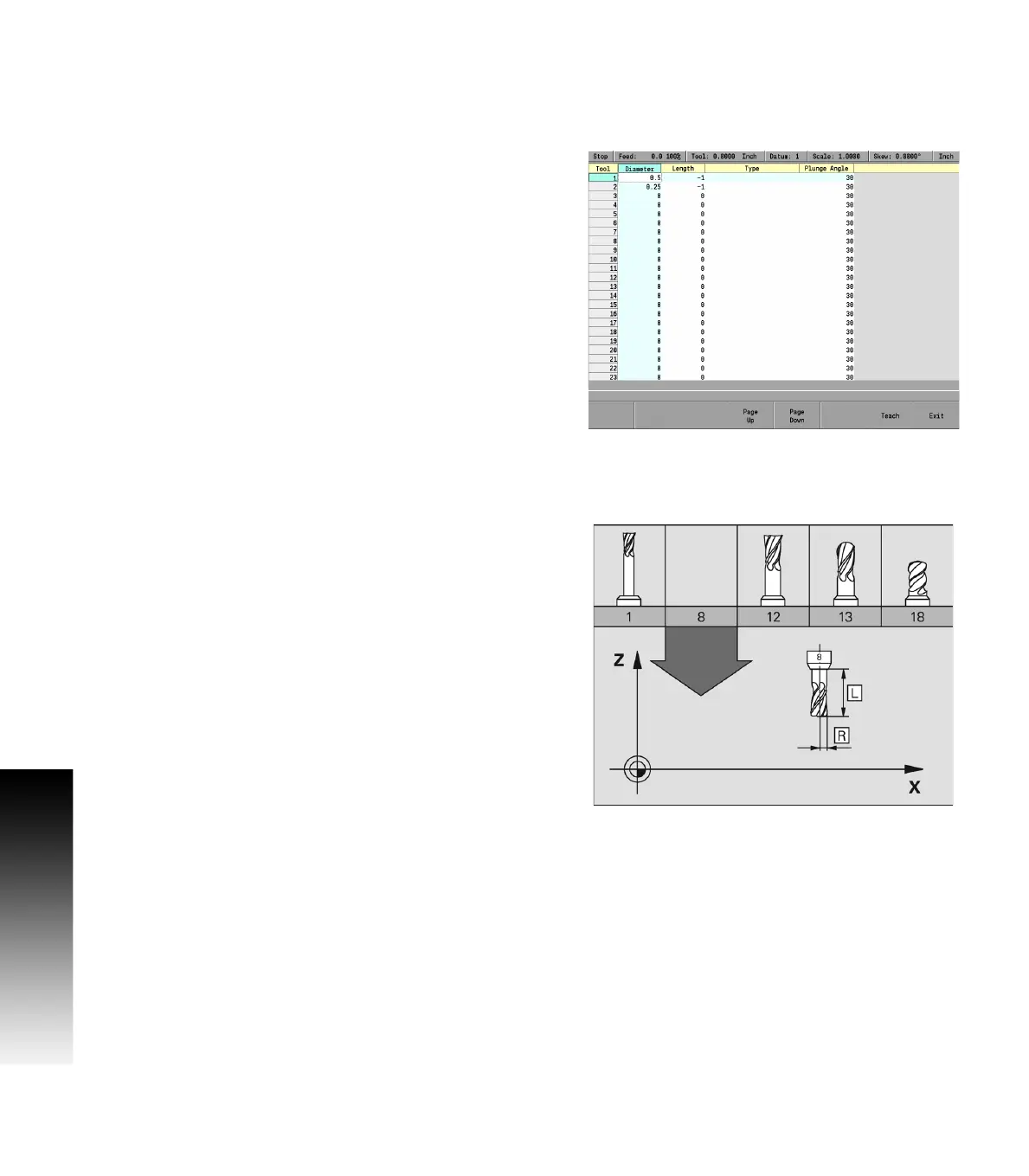
Tool compensation required data
You usually program the coordinates of path contours as they are
dimensioned on the work piece drawing. To allow the MILLPWR
G2
to
calculate the tool center path, e.g. the tool compensation, you must
also enter the diameter of each tool you are using.
Tool data can be entered either directly in the part program or
separately in the Tool Table. In the Tool Table, you can also enter
additional data for the specific tool. The MILLPWR
G2
will consider all
the data entered for the tool when running the part program.